Introduction
The natural resources exploitation triggers a process of continuous environmental degradation, since waste is produced during the raw materials extraction, as well as during the beneficiation [1,2]. The mining sector generates large residues quantities with various types and hazard levels [3]. In this context, the kaolin beneficiation industry has drawn a lot of attention from environmentalists, since it produces waste based on silica, mica and kaolinite in large quantities [4]. In the last years, the reuse development and practice has become expressive all over the world, aiming at new alternatives for the waste use, especially kaolin waste [5,6].
During primary kaolin processing, two types of waste are generated. The first is generated during mining, from the separation of the ore from the coarse sand, representing up to 70 % of the total produced. The second is the fine residue in the form of sludge, which comes from the second beneficiation stage, when the kaolin is purified [7]. Kaolin is one of the most used industrial clays worldwide, due to its excellent natural properties, such as: white color, very fine particle size, low abrasion and chemical stability [8,9]. As a consequence, the kaolin waste reintroduction into the production chain becomes interesting from an economic and environmental point of view, due to its good properties. The kaolin waste from the second beneficiation used as filler in polymers is an alternative, in view of the polymeric composites production [10,11].
The mineral fillers incorporation into polymeric materials has become increasingly common in the polymer industry [12].
Fillers are added to polymers to improve thermal, mechanical and thermomechanical properties, changing surface appearance and processing characteristics and, in particular, reducing the cost of the polymeric composition [13]. Currently, investigations are being directed towards the production of composites with biodegradable polymer matrix, such as poly(lactic acid) (PLA) and poly(ε-caprolactone) (PCL) [14-20].
PCL is a synthetic aliphatic polyester, derived from petroleum, biodegradable and biocompatible [21,22]. It is a semi-crystalline, flexible, hydrophobic, non-toxic material with good processability, suggesting potential for the production of sustainable composites [23]. The mineral fillers effect has been investigated on the crystallization behavior of PCL [24,25]. Siqueira et al. [26] showed that the montmorillonite clay accelerated the crystallization process of PCL, suggesting a nucleating effect. Paula et al. [27] developed PCL nanocomposites with zinc oxide (ZnO). The PCL crystalline melting temperature increased with the addition of up to 1 % ZnO, while a higher content began to decrease the melting temperature. Regarding the PCL crystallization temperature, there was an increase with the addition of 0.5 % up to 1 % ZnO, suggesting an acceleration in crystallization.
The technological interest of nucleating agents is mainly in the production cycle reduction, since it accelerates the polymers crystallization [28]. Injection molded products can be taken out of the molds warmer, reducing warping problems [29]. In view of this, kaolin waste is a raw material that needs to be analyzed as a nucleating agent. Regarding to PCL containing kaolin residue, no mention was found in the specialized literature, which is a relevant point to be investigated. The accelerating process of the PCL crystallization may be required in its applications and therefore the investigation has a practical interest.
This investigation aimed to evaluate the potential of kaolin waste with and without heat treatment in the structural and thermal behavior of poly(ε-caprolactone) (PCL).
Materials
Poly(ε-caprolactone) (PCL), marketed under the code Capa® 6500, molecular weight (Mw) 47500 ± 2000 g/mol (THF - 25°C), flow index (IF) of 28 g/10min (80°C/2.16kg), in pellet form and manufactured by Perstorp Winning.
The kaolin waste (KW) was obtained from the disposal after the beneficiation process for application in the paper industry, provided by the company CADAM S/A located in the state of Para. This material is widely used as filler for paper, since it is cheaper than cellulose pulp.
Methods
Beneficiation of kaolin waste
The kaolin waste was received unprocessed, in the form of a slurry; then it was dried in an oven at 110 °C for 24 h. Subsequently, it was subjected to grinding in hammer mills and clapper mills, in order to transform it into powder and reduce its granulometry. After grinding, the residue was passed through a 200 mesh (0.074 mm) ABNT sieve.
Thermal treatment of kaolin waste
The heat treatment induces phase transformations during firing, resulting in materials with chemical and dimensional stability, high durability, resistance to high temperatures and pressures [30,31]. To ensure a more crystalline phase formation, the beneficiated kaolin waste was subjected to heat treatment at a temperature of 1200 °C with a heating rate of 2 °C/min for a 2-hour firing step using an EDG 300 kiln.
Composites preparation
The kaolin waste and the PCL were dried in an air circulating oven at a temperature of 100 °C and 50 °C, respectively, for a period of 24 hours. The developed composite compositions are shown in Table 1, with the mass ratios (%).
Table 1 Composites compositions.
| Samples | PCL (% in weight) | KW (% in weight) | HTKW (% in weight) |
|---|---|---|---|
| PCL | 100 | - | - |
| PCL/KW | 99 | 1 | - |
| PCL/KW | 97 | 3 | - |
| PCL/KW | 95 | 5 | - |
| PCL/HTKW | 99 | - | 1 |
| PCL/HTKW | 97 | - | 3 |
| PCL/HTKW | 95 | - | 5 |
KW: kaolim waste; HTKW: heat-treated kaolin waste at 1200 °C.
The PCL/KW and PCL/HTKW composites were processed in a Thermo Scientific Haake Rheomix 3000 internal mixer, with roller-type rotors, under 80 °C temperature, rotor speed of 60 rpm and air atmosphere for 10 min. For comparison purposes, neat PCL was processed under the same conditions as the composites. The total mass (Mt) added in the mixer was determined using Equation 1:
Where: p = material density; 0,7 = volume occupied by the polymer mass in the mixing chamber (70%); Vn = total mixing chamber volume (310 cm3).
After melt processing, the material was ground in a knife mill and then dried at 50 °C in a vacuum oven. The samples were compression molded using 3 tons of load for 4 min. The samples cooling was performed in a room with a temperature of 18 °C, lasting 10 min. Figure 1 shows a scheme for obtaining composites.
Composites characterization
X-ray diffraction (XRD) analysis was performed on the compression molded samples (3 mm thickness), conducted in a Bruker D2 Phaser diffractometer, using copper Kα radiation, 30 kV voltage, 10 mA current, 2θ scan from 10° to 70° and scan speed of 2°/min. The crystallite size (CS) was calculated by means of the Scherrer equation (2), using the DIFFRAC.EVA software and adopting the most intense basal reflection peak [31]:
Where: CS is the average crystallite size; k is a constant that depends on crystallographic factors of sample shape and reflection (0.89); A is the wavelength of the radiation; (3 is the width at half height of the diffraction peak; a is the Bragg angle.
The differential exploratory calorimetry (DSC) analysis was performed in a TA Instruments DSC-Q20 apparatus. The test was performed on compression molded samples starting from 0 to 100 °C, under heating rate of 10 °C/min and isotherm of 3 min, gas flow of 50 mL/min, under nitrogen atmosphere and using 6 mg of sample. The degree of crystallinity (Xc) was calculated using Equation 3[32]:
Where: ∆H m= Crystalline melting enthalpy obtained by DSC; ∆H f = Melting enthalpy of PCL with 100% crystallinity, 146 J/g [33, 34]; w = mass fraction of PCL in the composition.
The phase transition events (melting and crystallization) obtained by DSC were analyzed using the INTEGRAL software, as described in the literature [35-37]. The conversion into melt fraction and crystallized fraction was made using the Equation 4
J corresponds to the heat flow required during the phase transition event, while J0 represents the virtual baseline. Moreover,
E 0 indicates the total energy released during the exothermic crystallization event and, at the same time, the terms t1 and t2 represent the initial and ending times of an event. Regarding the melting and crystallization rate (c) [38], the mathematical equation is given by Equation 5
Results and discussion
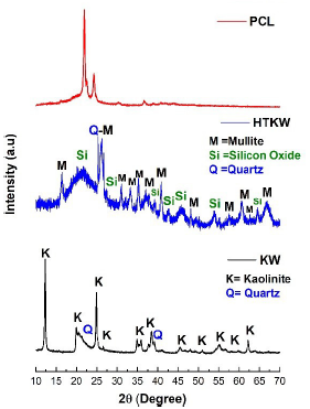
The X-ray diffraction (XRD) technique has been widely used for the crystalline phases determination, as well as the degree of crystallinity [39,40]. Figure 2 shows the PCL, KW and HTKW diffractograms, respectively. The degree of crystallinity and crystallite size are summarized in Table 2.
Neat PCL showed two crystalline reflection peaks, which appear centered at 2θ = 21.8° and 23.9°, that correspond to the crystalline planes (110) and (220) [41], respectively. The crystallinity and crystallite size of PCL were 52.8% and 25.1 nm, respectively. For the kaolin waste (KW), well-defined and high-crystallinity peaks are observed and are attributed to triclinic kaolinite (KAl2Si3AlO10(OH)2) and hexagonal quartz (SiO2), both identified by PDF 01-078-2110 and PDF 00-046-1045, respectively. Similar results have been reported in the literature [42], indicating the presence of kaolinite and quartz in kaolin waste. The heat treatment at 1200 °C effect on the kaolin waste promoted the nucleation of new crystalline phases, an effect verified in the literature [43]. The heat-treated kaolin waste showed mullite, quartz, and silica-rich amorphous phase, according to PDF 01-074-4145, PDF 01-080-2147, and PDF 00-014-0260, respectively.
In Table 2, the kaolin waste showed a crystallinity of 73.8 % and a crystallite size of 37.8 nm. With the application of heat treatment at 1200 °C in the kaolin waste (HTKW), the crystallinity decreases considerably, reaching 45.4%, which is related to the amorphous phase appearance, consisting mainly of silica [44]. In addition, the kaolin waste treated at 1200 °C crystallite size reduced to 16.98 nm, suggesting the formation of less perfect crystals. This behavior is confirmed with the increase in the background in the 29 region between 20° and 30°, as verified in Figure 2.
Table 2 Degree of crystallinity and crystal size of neat PCL, KW and HTKW.
| Samples* | Crystallinity (%) | Crystallite size (nm) |
|---|---|---|
| PCL | 52.80 | 25.10 |
| KW | 73.80 | 37.80 |
| HTKW | 45.40 | 16.98 |
*PCL: poly(e-caprolactone); KW: kaolin waste; HTKW: heat-treated kaolin waste.

Figure 2 XRD diffractograms of neat PCL and kaolin waste with and without heat treatment, respectively.
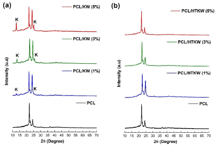
Figure 3 shows the diffractograms obtained by XRD of the PCL/KW and PCL/HTKW composites, respectively. It was observed that the composites PCL/KW and PCL/HTKW, regardless the filler content, showed the same diffraction peaks referring to the PCL crystalline phase, in the range of 2θ ~ 20° to 25°, indicating that the kaolin waste did not alter the PCL crystalline structure.

Figure 3 XRD diffractograms of the composites: (a) PCL/kaolin waste; (b) PCL/heat-treated kaolin waste.
The development of PCL composites with kaolin waste (KW) promoted the kaolinite crystalline peaks appearance, as shown in Figure 3(a). On the other hand, the addition of heat-treated kaolin waste (HTKW) to PCL did not impact the appearance of crystalline peaks of mullite, quartz or silica, due to the low intensity as verified in Figure 2. Regarding the PCL crystalline peaks intensity, there was an increase at 29 = 23.9° of the PCL/KW composites compared to neat PCL. Such behavior was due to the additive effect of the kaolinite main peak, since it coincides with neat PCL. The incorporation of up to 1% HTKW in PCL increased peak intensity by 2θ = 23.9◦. Contrarily, the PCL/HTKW (3 and 5 %) composites tended to reduce the peak 2θ = 23.9◦ intensity, especially with 5% HTKW. Since the quartz crystalline peak has high intensity and overlaps that of PCL, it becomes reasonable to suggest that the decrease in the 23.9◦ peak was due to the presence of the silica-rich amorphous phase, which hinders the PCL crystallization. Apparently, since amorphous silica presents a disorganized structural arrangement [45], it generated an inhibition in the crystallization of PCL, corroborating with the crystallization temperature obtained by DSC.
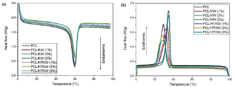
The DSC curves obtained during the second heating cycle can be seen in Figure 4 (a,b). Table 3 presents the neat PCL and the composites melting parameters, crystallization and the degree of crystallinity.

Figure 4 DSC curves for the neat PCL and the composites: (a) melting temperature; (b) crystallization temperature.
Table 3 Melting and crystallization parameters of neat PCL and composites Tc: Crystallization temperature; ∆H m: Crystalline melting enthalpy; X c : Degree of crystallinity .
| Samples | Tm (°C) | Tc (°C) | A Hm (J/g) | Xc (%) |
|---|---|---|---|---|
| PCL | 59.9 | 29.1 | 47.4 | 32.5 |
| PCL/KW (1%) | 59.9 | 33.4 | 43.7 | 30.2 |
| PCL/KW (3%) | 59.9 | 34.7 | 45.7 | 32.3 |
| PCL/KW (5 %) | 60.3 | 34.6 | 43.6 | 31.4 |
| PCL/HTKW (1 %) | 60.0 | 31.4 | 47.8 | 33.0 |
| PCL/HTKW (3%) | 60.5 | 27.9 | 45.1 | 31.8 |
| PCL/HTKW (5%) | 60.7 | 29.2 | 38.8 | 28.0 |
The crystalline melting temperature (Tm) of PCL was approximately 59.9 °C, close to the values determined in the literature [46,47]. The composites PCL/KW and PCL/HTKW, regardless of the filler content, did not significantly change the Tm compared to neat PCL, there was only a maintenance of the values. The heat treatment effect on the kaolin waste (HTKW) did not promote a sharp change in Tm in the PCL/HTKW composites, since the values are comparable to the composites containing KW. Such behavior suggests that the PCL crystalline melting point was not affected by the nucleation of mullite in the heat-treated kaolin waste.
Regarding the crystallization temperature (Tc), the value found for pure PCL was around 29.1 °C, as also verified in the literature [29,46]. The addition of 1 to 5 % of kaolin waste (KW) promoted a shift of the curves to higher crystallization temperature, in the range of 33.4 °C to 34.6 °C. In view of this, kaolin waste (KW) has the potential to accelerate the crystallization process of PCL, since PCL/KW composites started to solidify at higher temperature. From a technological point of view, kaolin waste can favor the production cycle reduction of PCL-based parts. This means that injection-molded products can be extracted hotter from the molds, since they solidify at higher temperatures [48]. It was observed that the heat treatment of kaolin waste (HTKW) negatively affected the crystallization temperature of PCL as it was lower than the results of kaolin waste (KW). The addition of up to 1 % of HTKW in PCL shifted the temperature to 31.4 °C, indicating that it still accelerates the crystallization process compared to neat PCL. However, the composites containing the 3 % and 5 % HTKW concentrations had an inhibition in crystallization temperature compared to PCL, confirming the trend seen in XRD. Apparently, the amorphous silica-rich phase formation during the heat treatment of kaolin waste compromised and reduced the crystallization process of PCL. This finding becomes important from an economic point of view, since the kaolin waste can be used unprocessed, aiming to accelerate the crystallization of PCL. The PCL degree of crystallinity (Xc) indicated a value of 32.5 %, a value lower than that verified in XRD, due to the difference in measurement of each equipment. The PCL/KW and PCL/HTKW composites had slight non-significant changes in the degree of crystallinity compared to PCL, except for the PCL/HTKW composition (5 %) which reduced more severely (28 %). As the PCL/HTKW (5%) composites presented a greater amount of amorphous silica fraction, there was a greater inhibition of crystal nucleation. In view of this, the addition of higher concentration of the heat-treated kaolin waste negatively impacts during the molecular organization of PCL for the formation of crystals.
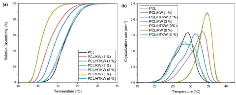
Figure 5 (a, b) shows the relative crystallinity and crystallization rate of neat PCL and composites as a function of KW and HTKW, respectively. PCL and PCL/HTKW composites showed similar behavior in relative crystallinity, except for the composition containing 1 % HTKW, which started to crystallize at higher temperature. Apparently, 1 % HTKW was a critical concentration, since above this value the relative crystallization was inhibited. Such behavior suggests that 3 % and 5 % HTKW in PCL already has an amount of silica-rich amorphous phase that hinders crystallization. The PCL/KW composites showed higher relative crystallinity at higher temperature compared to PCL and the PCL/HTKW composites. This is advantageous during the injection molding process, as the products solidify earlier. The same trend was observed for the crystallization rate. PCL/KW composites have higher crystallization rates at higher temperature, especially with 3 % and 5 % KW. PCL and PCL/HTKW composites showed slower crystallization rate, indicating that they need more time to crystallize.

Figure 5 Crystallization kinetic curves of PCL and composites. (a) Relative crystallinity; (b) Crystallization rate.
Figure 6 (a, b) shows the molten fraction and the crystals melting rate behavior, respectively. The melt fraction curve of PCL and composites showed sigmoidal characteristic, suggesting continuous phase transition [36]. The PCL/KW and PCL/HTKW composites started to melt at slightly higher temperature compared to neat PCL. In relation to the melting rate (Figure 6 [b] ), there were no significant variations, only subtle changes. This indicates that the melting temperature was practically unaffected, confirming Figure 4 (a).
The composites torque rheometry analysis is important, since it can suggest changes in the processability of neat PCL. Figure 7 shows the torque rheometry curves of the neat PCL and the composites as a function of 1%, 3%, and 5% KW and HTKW contents, respectively.
In Figure 7, it was observed that in the early stages of the processing of neat PCL and composites, the torque reaches a maximum peak, due to the material compaction as it is in solid state [49]. During processing, the kaolin particles rubbed against each other and against the mixer chamber walls, and the PCL plastic deformation [50]. As a consequence, to maintain the same rotation speed, more mechanical work was required, which caused a significant increase in torque [51]. After melting, the PCL starts to flow and the kaolin particles are involved by the PCL matrix. In this case, the energy dissipation becomes predominantly viscous friction between fluid layers, causing the torque to decrease until it stabilizes [52]. Thus, the stable torque values can be used as processing indicators for the PCL/KW and PCL/HTKW composites. After torque stabilization at 2 min processing, the values are slightly higher for the composites containing kaolin compared to neat PCL. However, the addition of 1 to 5 % of KW and HTKW did not promote a significant modification in the torque values, since they are close to those of neat PCL. Therefore, the presence of kaolin particles at the concentrations used did not significantly modify the PCL processability. This finding becomes important from an economic and environmental point of view, since it can add value to an industrial waste that would otherwise be discarded in the environment. The heat treatment effect on the kaolin waste did not affect the composites torque behavior, as there was no significant change compared to the materials containing kaolin waste without heat treatment.
Conclusions
The feasibility of reusing kaolin waste with and without thermal treatment was evaluated on the structural and thermal behavior of PCL. The parameters of crystallization temperature, relative crystallinity and crystallization rate were improved with virgin kaolin waste. In addition, the crystalline melting temperature and processability were hardly changed significantly, indicating that low concentrations of kaolin waste did not promote drastic changes in these properties. At the same time, the effect of heat treatment up to 1200 °C on the kaolin waste proved unnecessary to produce composites with PCL matrix. This behavior was due to the silica-rich amorphous phase, which impaired the crystallization process of PCL. Given this, natural kaolin waste is a promising raw material to accelerate the crystallization process of PCL. In general, the reuse of kaolin waste as an additive to PCL is an alternative to reintroduce it into the production chain, with the possibility of adding value to an abundant and discarded raw material. The results presented are valuable for the area of materials recycling, considering the potential of kaolin waste for the polymer additive industry.


