


 English (pdf)
 Article in xml format
 Article references
 Send this article by e-mail
 Cited by SciELO
  Cited by Google
  Similars in
SciELO
Similars in
SciELO  Similars in Google
 Permalink
1. INTRODUCTION
Crude oil is the largest and most commonly used energy source in the world, mostly as fuel for transport, including gasoline, diesel and jet fuel. Nevertheless, such crude oils contain sulphur, typically in the form of organic compounds [1]. The atmospheric contamination caused by sulphur oxide emissions (SOx) is one of the most serious global environmental problems [2]. The exhaust gas of motor vehicles is the main source of sulphur oxides, formed in the combustion of gasoline and diesel due to the presence of sulphur [3], in particular thiophene, which is one of the main components [4] along with its derivatives.
These sulphur compounds are responsible for the acid rain that is formed by the reaction of sulphur dioxide and nitrogen oxide released with water molecules into the atmosphere and, likewise, causing atmospheric haze and photochemical smog [5], which are the main source of atmospheric pollution and, hence, of the general environment, jeopardizing not only human health, but also all living organisms [6]. Consequently, several developed countries have planned to obtain little or nil sulphur fuel (content of S <10 ppm) to reduce the emission of sulphur dioxide, developing alternative ultra-deep desulphurization processes such as adsorption, extraction, oxidation and bioprocesses [7].
The problem of gasoline deep-desulphurization has aggravated over time as refined crude oils from petroleum extraction show sulphur contents that are gradually higher and, furthermore, the environmental regulations limit the sulphur content in fuel at lower limits [8]. Therefore, industries working with these types of contaminated substances are seeking the best alternative for their elimination.
Furthermore, the most conventional and most used desulphurization method is hydro-sulphurization (HDS), which has been broadly used to eliminate sulphur-containing substances. However, the high temperature and pressure, as well as the hydrogen used, translate into cost increases [9]. This technology eliminates most of the sulphur content such as thiols, sulphur, bisulphur and other sulphur components, but some sulphur contents in fuels such as aromatic thiophenes are difficult to eliminate through the typical HDS [10].
Other methods, such as biodesulphurization (BDS), adsorption desulphurization and extraction desulphurization (EDS) have been subjected to research seeking deep desulphurization (<5 ppm). Among these methods, the oxidative desulphurization (ODS) is one of the most promising ways for supplementing the HDS because of its moderate operating conditions, low cost, and no hydrogen use [11].
However, the photocatalytic oxidative desulphurization (PODS) is considered one of the most promising desulphurization methods given its mild reaction conditions, its high efficiency [12], high selectivity and high rate of desulphurization of thiophene and its derivatives [13]. This technique uses semiconductors such as titanium dioxide, which has been widely studied as a photocatalyst to oxidize dibenzothiophenes and its derivatives in diesel [14] and is mostly used for its high availability, chemical stability, low cost and excellent photocatalytic activity under UV radiation [15]. Additionally, it is a highly promising desulphurization technology for diesel considering its already proven results in the oxidation of various organic compounds [16]. This is a new accessible degradation method and, given the operating conditions, it is economic and viable to obtain satisfactory degradation and applicability in various industries.
In desulphurization processes, it is very important to continuously monitor the concentration of sulphur compounds while carrying out the experiments. Currently, there are different methods available for measuring total sulphur, with its species, but unfortunately only a few are useful at ppm concentration levels [17].
The most commonly used methods for determining sulphur components are titration, colorimetric, chromatographic, iodimetric and X-Ray fluorescence spectroscopy. Even though such methods are accurate and sensitive for determining elemental sulphur, they require much time and are tedious. In comparison with these methods, electrochemical procedures are highly promising as they achieve high sensitivity at a good speed, low cost, and low detection limits [18].
Furthermore, in the chemical analysis of this type of sulphur compounds, the chromatographic methods that are used for separation and characterization of oil derived compounds do not provide direct information on the level of oxidation and the degradation mechanisms of said compounds in the samples. In this context, the electro-chemical methods are a useful tool for monitoring and controlling electroactive species [19]; therefore, in parallel with the desulphurization, an electrochemical method of analysis was implemented to track the variation of thiophene concentration during the photocatalytic degradation. Because the thiophene or its derivatives polymerization can be performed through an oxidative process on an electrode (usually carbon), via radical ions, it is thus possible to monitor the thiophene concentration in solution by means of an electrochemical method [20]. In general, for characterizing materials, the cyclic voltammetry is used, but for quantification purposes it is better to use other techniques such as differential pulse voltammetry (DPV) or the square wave voltammetry (SWV). In general, the electrochemical analysis procedures are much simpler, cheaper and can be easily implemented.
This paper presents the implementation of an electrochemical method for monitoring of thiophene concentration during its catalytic photodegradation in a model fuel, which in this case was a solution of thiophene in iso-octane. Within the wide range of electrochemical techniques, we decided to use the differential pulse voltammetry due to its high selectivity and sensitivity, added to its low detection limits. This is because in the measured response (current intensity) the contribution of the electrical double layer is eliminated almost entirely (capacitive current), resulting in a current signal that depends exclusively on the thiophene electrochemical process on the working electrode of the analysis cell (faradaic current). The implementation of this analysis method for monitoring the thiophene concentration during the desulphurization is considered an innovating method as it is not the usual methodology for this purpose.
2. EXPERIMENTAL DEVELOPMENT
To obtain photocatalytic films, microscopy sodium-calcium glass slides were used (3.8 cm long, 2.5 cm wide and 1 mm thick), TiO2 Hombitan type, polyethylene glycol, isopropanol, AgNO3 and deionized water. A suspension was prepared with 5 g of TiO2, 2 g of polyethylene glycol and 15 ml of isopropanol; the thin films were placed on the slides by spin-coating at 3000 rpm for 20 seconds, adding 20 suspension droplets. Finally, a thermal treatment at 600 °C was applied for 90 minutes.
Next, the doping of the TiO2 films was performed by means of a photochemical reduction, where these are immersed in an aqueous silver nitrate solution (0.025 g of AgNO3 in 5ml of deionized water) and subsequently irradiated with UV for 30 minutes, forming an adsorbent with excellent sulphur adsorption capacity for commercial fuels [21]. The films color changes from white to grayish brown, which indicates the transformation of the material [22].
The TiO2 thin films were characterized through photocatalytic degradation of methylene blue, obtaining degradation percentages of 97.16% (Ag/TiO2 + O2), 97.7% (TiO2 + O2), 94.76% (Ag/TiO2) and 93.74% (TiO2). As UV light is approximately 4% of the solar spectrum and can be easily filtered, it is necessary to modify the interval between the valence band and the conduction band of TiO2 to enhance its optical properties [15].
The laboratory-scale photocatalytic reactor was made up of a borosilicate cylindrical glass vessel, which size is 5 cm long, 4.7 cm outer diameter, and approximately 3 mm wide; a Teflon cap to support the film-holder, the three electrodes for electrochemical determination of thiophene, and the UV lamp (one 3 W led connected to a 5 V and 1 A current adapter), which is immersed in water at ambient temperature in a cylindrical glass vessel to control temperature and prevent the evaporation of the solution. The reactor assembly schematics is shown in Figure 1.

Figure 1 Photo-reactor assembly schematics with the following components: A-cylindrical borosilicate glass vessel, B-Teflon cap, -glassy carbon as work electrode, D-film holder support, E-UV lamp and F-cylindrical glass vessel.
Differential pulse voltammetric measurements were carried out using the BAS CV-50W electrochemical analyzer system. Three-electrode electrochemical cell was used with 3 mm diameter glassy carbon disc as working electrode, a silver wire as pseudoreference electrode and a platinum wire as auxiliary electrode. Acetonitrile (ACN) was used as solvent and tetrabutylammonium hexafluoroborate (TBAHFB) as supporting electrolyte.
For thiophene electrochemical determination, differential pulse voltammograms were recorded, while the potential were scanned from 1000 mV to 2500 mV (vs. Ag/Ag+). Figure 2 shows the voltammogram obtained for a solution of 25.0 ppm in thiophene. The anodic current peak appearing at about 1820 mV (vs Ag/ Ag+) corresponds to the oxidation process of the sulphur atom in thiophene to a sulfoxide and subsequently to a sulfone.

This is a common oxidation mechanism for thiophene and its derivatives, which allows for its detection and quantification, even in the presence of other sulfur compounds [23]. Two experimental strategies were used for the quantification of thiophene in the photocatalytic reactor:
PROCEDURE TAKING ALIQUOTS FROM THE SOLUTION.
For the study of the thiophene photocatalytic degradation, a solution of 12306 ppm of thiophene in isooctane was prepared. As the isooctane has a very small dielectric constant, it is not a good solvent for electrochemical studies and this prevents the electrochemical direct monitoring of the thiophene concentration (in-situ) in the photocatalysis cell. In the initial trial to assess the effectiveness of the photocatalytic degradation of thiophene, 25 μL aliquots were taken from the solution and transferred to an electrochemical cell containing 10 mL of a 0.01 M solution of the support electrolyte in acetonitrile; this solution also contained iso-octane 1%. The three electrodes are immersed in this solution and the potential sweep with DPV is applied, measuring the peak oxidation current, IP, which is proportional to the thiophene concentration in the medium. Hence, 25 μL aliquots are transferred from the photo-reactor solution, every half hour, to the electrochemical cell that contained at all times 10 ml of the HFBTBA solution in ACN. Each determination was trebled, changing each time the solution in the cell and carrying out an electrode cleaning process.
Previously, a calibration curve was built of IP in function of the thiophene concentration (in ppm), the results of which are shown in Figures 3 and 4.
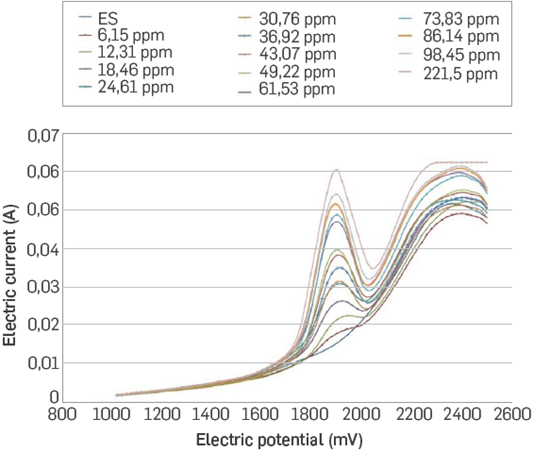

Figure 3 shows voltammograms obtained through DPV for the calibration curve. The peak current is determined automatically, using the machine's software.
IN-SITU PROCEDURE.
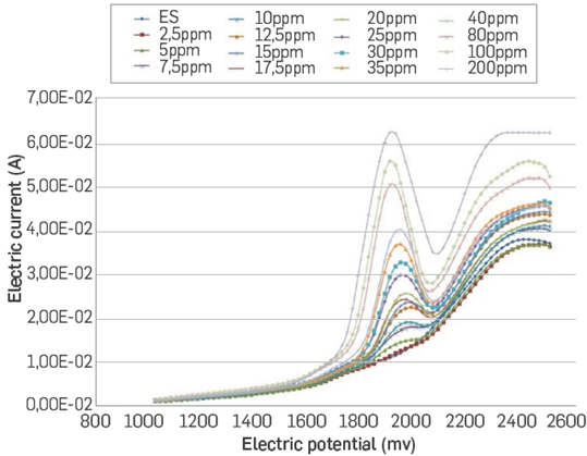
In the second trial, trying to track thiophene within the same photocatalysis cell, the composition of the cell for degradation was modified making it suitable for the electroanalysis process. For this procedure, it was necessary to prepare three solutions. The first was a mixture of acetonitrile (90% p/p) and iso-octane (10% p/p). The second, a 1000 ppm thiophene solution in the acetonitrile-iso-octane mix. Finally, the solution for the photocatalytic study and in-situ electro-chemical determination was prepared; this solution was 0.01 M in HFBTBA and it contained 100 ppm of thiophene, all of it dissolved in the acetonitrile iso-octane mixture. The three electrodes of the electrochemical cell are immersed in this solution, together with the UV lamp. The determinations of thiophene concentration were made by DPV in the same conditions mentioned above. Previously, a calibration curve was constructed with thiophene standard solutions with the same composition of solvent and support electrolyte used for the photocatalysis study. The results obtained for the calibration curve of the in-situ method are shown in Figures 5 and 6.

3. RESULTS ANALYSIS
PROCEDURE TAKING ALIQUOTS FROM SOLUTION.
The quantification of thiophene in the mixture was performed every thirty minutes during the first two hours of photodegradation and, subsequently, the measurements were taken every hour until completing 7 hours of the desulphurization process. Figure 7 shows the evolution of the thiophene content in the reactor throughout the photocatalytic degradation process.

As evidenced in this graph, the thiophene concentration decreased, down to 20 ppm, that is to say it reduces nearly 38% the contaminant concentration, which enables us to determine that the photocatalytic desulphurization procedure works and that it could be implemented at a greater scale to assess its feasibility in industrial processes. Of course, it is necessary to further study the physicochemical aspects of the phocatalytic process to enhance its results, because, for example, as observed in the results of the graph in Figure 7, the photocatalyst becomes passive after a 6-hour work.
IN-SITU PROCEDURE.
Measurements were taken for a total 4-hour period; the first four determinations were made every half hour and thereafter every hour.
Before starting the measurement, the work electrode was subjected to a cleaning process. The results obtained are shown Figure 8.

Given the process conditions, the thiophene concentrations used were higher than in the previous case. There is no evidence here of the photocatalyzer becoming passive, and there is a reduction of thiophene concentration from about 72 ppm to about 40 ppm, that is, there is 43.9% thiophene degradation. Because the initial and operating conditions during this procedure were different than in the first case, we cannot compare them, but we can prove the effectiveness of photocatalysis as a desulphurization method in oleic solutions and using modified TiO2, as evidence in the works of Lu et al. [5], Dedual et al. [8], Lin et al. [2] and Liu, Min, Hu and Liu [24].
The photocatalytic activity takes place as of the irradiation Ag/ TiO2 with UV light, as it provides sufficient energy for excitation of the electrons from the valence to the conduction band, creating electron-hole pairs. Several authors suggest that the thiophene oxidation mechanism in non-aqueous medium and in the presence of molecular oxygen must occur through the formation of a radical cation, on the sulphur atom, with the subsequent formation of a sulphane that decomposes finally to SO3 [2], [25]-[27]. The electron-hole pair formed separates and the molecular oxygen, absorbed on the TiO2, reacts with the photo-generated electron producing the highly reactive species O2 •- and O2 2-, which are responsible for the degradation of thiophene to SO3. In the total thiophene catalytic photooxidation reaction, CO2 and SO3 are produced. Therefore, as described in the work of Abdelaal and Mohamed [4], Baeissa [15] and Mohamed and Azam [28], the thiophene photocatalytic conversion will be:
Thiophene + photocatalyzer ---► CO2 + SO3 + H2O (1)
In general, besides achieving desulphurization from the implementation of a photocatalytic process, an electroanalytical method was developed and implemented for constant monitoring of thiophene in fuels, which is supported by the works of Mostafavi et al. [29], Anber, Milde, Alhalasah, Lang and Holze [30] and Çelik et al. [31], obtaining similar results for thiophene determination.
CONCLUSIONS
A new electroanalytical method was implemented for monitoring the photocatalytic degradation of thiophene, which is low-cost, easily implemented and which allows to perform in situ measuring of thiophene concentration during this process.
The photoreactor implemented enables the degradation of the main sulphur contaminant in gasoline (Thiophene) up to 37.94% in the isooctane thiophene mixture and up to 43.88% in the modified mixture for in situ electrochemical monitoring.

