1. INTRODUCTION
While drilling, the bit cuts the rock from the subsurface and drilling mud transports those drill cuts (called cuttings) from the bottom to the surface. The size of a cutting varies from a few microns to a few millimeters (usually less than 5). Usually, if the borehole starts to fail, it produces cavings and those cavings are rock masses that are larger than 5 mm and can be as big as 30 cm in length (with a mass of more than 2kg). Due to the size and amount of cavings produced, the drilled well might be lost and it can result in a great deal of unexpected expenditure, time and other resources for the drilling company. Due to these reasons, cavings and cuttings must be measured during the drilling process in order to prevent wellbore instability, keep drilling operations under control and maintain costs within the operating window.
Geomechanics experts use information regarding the amount of rock per time-unit to establish the wellbore stability [1]. In particular, an estimate of the caving volumetric-flow in bbl/min (barrels per minute) indicates the stability status of the wellbore. A high level of volumetric flow can indicate instability in the hole, and corrective actions should be taken before an accident occurs [2].
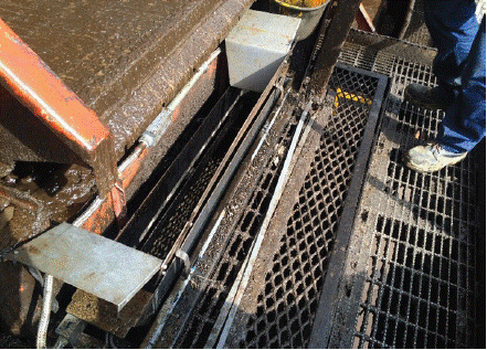
Traditional methods used to estimate cavings flow use a manual technique in which people take samples at the shaker during a time interval and compute cavings and cuttings flow using theoretical data on wellbore geometry and measured weights of samples. In recent years in Colombia, a mechanical instrument known as MAC (Medidor Automático de Cavings, as it is called in Spanish) is used to measure the amount of rock that is extracted from a wellbore in a typical well-drilling process [3]. The MAC has a reception device where the rocks are collected after the mud is filtered, and it collects such rocks during a time lapse and measures the weight of the rocks collected. Afterwards, a gate is opened, so that the rock is released, and the weighing process starts again. This system measures the weight of the rock transported by the drilling mud, but this method is not exact because the rock is impregnated with drilling mud. Some rock mass can be lost between two consecutive measurements and part of the drilling mud stays in the measurement equipment, thus altering the weight of rock mass to be measured. Figure 1 shows the MAC instrument installed in a wellbore while drilling operations are performed.

Figure 1 MAC Operation while drilling. Example of a MAC installed at the shaker. The container collects rocks before opening a gate to release them, and start a new time lapse for rock collection. Afterwards, the volume of rock is calculated using density and weight of the samples collected, and volumetric flow corresponds to this volume per time unit.
The measurement of the volumetric flow of cuttings and cavings obtained with the MAC instrument has delivered good results when compared with the measurements of the size and shape of a borehole, registered by the caliper log. However, the maintenance of the instrument is particularly laborious because the drilling mud attaches to the gate, thus not allowing the container to be opened to release the rock. Additionally, different types of shakers require different adaptations of this instrument, so that it fits precisely for each type of shaker.
The proposed system is a non-invasive method that measures caving and cutting volumetric-flow in such a way that maintenance issues and the design restrictions of the MAC instrument can be avoided. The proposed measurement mechanism uses a piezo-electric transducer configuration in the flow line, such that the amount of rock per minute (in terms of cubic meters per time unit) can be estimated using the Doppler effect. The Doppler effect states that if an object emitting an acoustic source is moving, then an observer perceives changes of the wave frequency of the source due to its relative velocity with respect to the emitter [4]. This phenomenon makes it possible to estimate the velocity of the mud and particles of rock that are passing through a cross-section of the pipeline. Knowing the velocity of propagation of the mud and particles, we can generate a model that relates the frequency change with the volumetric flow of rocks. This model is different for different sizes of rock transported inside the mud in the pipeline. Thus, a geomechanics expert can use this model to determine the amount of rock (per time unit) that is being transported, and identify whether there is a risk of the wellbore collapsing.
In order to experimentally test the proposed strategy for volumetric-flow estimation, an experimental system that emulates the rock transport by the drilling mud through the flow line was built, and two different sizes of rock where tested. The frequency shift observed in the acoustic sensors for different quantities of rock was measured in the experiments, to thus obtain a model of frequency change as a function of the volumetric flow of rock. This model was validated using additional experiments in which a known amount of rock was inserted into the flow line and the volumetric flow was measured and compared with the values given by the model.
2. THEORETICAL FRAME
The theory behind the proposed method for measuring volumetric flow of rock through the flow line is the acoustic-wave propagation phenomena, in which the acoustic wave is propagating through a medium that contains solids traveling at a certain velocity. Acoustic signals have been widely used in many applications to estimate flow [5], for instance, in the estimation of fluids-flow velocity in industrial pipelines [6]-[8], or to understand the blood flow in veins and arteries in medical applications [9] and [10]. A traditional method used for the estimation of the volumetric flow is the Doppler effect. In addition to the Doppler effect, other techniques (such as those based on the arrival time of the acoustic signals, or the cross-correlation between emitted and received signals) can also be used for volumetric flow estimation.
DOPPLER EFFECT
The Doppler effect states that a particle (source), which is moving through a specific medium, produces a frequency change for an observer who is moving with a relative velocity with respect to the emitter. Thus, determining the change in frequency makes it possible to establish the relative velocity between emitter and observer.
Assume that a particle E with a specific speed v is moving towards an observer R1, and away of an observer R2 (See Figure 2-left). The moving particle E (or source) emits a continuous pressure signal, which travels with a speed c, depending on the medium. The observer R1 detects a pressure signal having a frequency that is larger than the one detected by the observer R2 [11]. This phenomenon is known as Doppler effect and it is given by
Where f O is the frequency of the pressure signal at the observer, fe is the frequency of the emitted pressure signal, fd is the change in frequency and C is the speed of light in a vacuum.
Now, if a particle is traveling through a pipeline (see Figure 2-right), then the particle becomes an emitter when a piezo-electric crystal emits a signal that reaches the particle. Assuming that the crystal is emitting a pressure signal at point F and the receiver transductor is located at R1. Then, the pressure generated by exciting the crystal in F, travels through the medium reaching the particle E and this becomes a source by scattering a pressure signal that reaches the receiver transducer in R1. Since the particle is moving in the pipeline with a specific speed v, then the signal that is measured at the receiver is shifted in frequency, in comparison to the transmitted signal. For this case, the geometry given by the location of the transducers should be included in the equation and the change in frequency is given by [11]:
where a is the angle between the straight line along which the particle is moving, and the straight line between particle and receiver. Note in Eq. (2) that when the change in frequency and the frequency of the emitted signal are known, then the velocity of the particle can be found as
Furthermore, the volumetric flow of particles Q, that are traveling through a given cross-section of the pipeline is given by
Q= vA (4)
where A is the area of the cross-section of the pipeline.
FREQUENCY OF AN ACOUSTIC WAVE
As seen previously in the equations that govern the estimation of the volumetric flow using the Doppler effect, the correct estimation of the frequency change becomes a major issue, and a small error in the estimated frequency may lead to an error in the velocity of the particle in the order of hundreds of meters per second. The frequency resolution obtained during the experiment is given by
Where N and T is the number of acquired samples and period respectly, the maximun-fequency (fmax) is obtained at maximum period (Tmax). The maximum frequency in the transformation depends on the sampling frequency f s. Note in Eq. (5) that in order to improve the resolution in frequency, it is necessary to either decrease the maximum observable frequency in the transformation or increase the number of sample points in time.
The frequency of the emitter can be obtained knowing the resonance frequency of the piezo-electric crystal, which is the natural-vibration frequency. The Fourier Transform (or its fast version, the FFT) of the time signal is used to determine the resonance frequency of the piezo-electric crystal.
ACOUSTIC IIMPEDANCE
In addition to the estimation of the frequency change and frequency of the emitter, It is also necessary to know the path of the acoustic ray when It is traveling through a medium. When a pressure wave changes medium, there is change in the path due to the refraction phenomena. This change in the path arises due to the presence of acoustic impedance.
The acoustic impedance Z can be obtained as the product of the speed of the sound c in a given medium and its density, i.e., Z=cp The difference in the acoustic impedance between two mediums affects the signal that is reflected and transmitted. A high reflection coefficient means that most of the signal is reflected rather than refracted The refraction and reflection phenomena are illustrated in Figure 3. The refracted signal has a direction that depends on the angle of the incident wave and the medium characteristics. Snell's law governs this behavior.
3. EXPERIMENTAL DEVELOPMENT
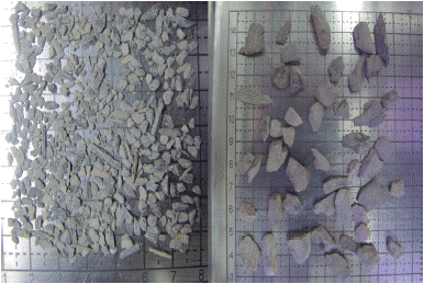
The experiment was designed to resemble the flow line conditions while drilling. Therefore, the cavings size and typical flow values were needed to establish the size and quantity of rock to be used in the experiment. These data were obtained from historic information recorded from wells drilled in Colombia. Table 1 sets out the amounts and sizes of rock, as well as concentrations in the mud-rock mixture. Furthermore, Figure 4 shows a picture of both sizes of rock used in the experiment. Additionally, all the experiments required 20 Liters of mud with characteristics similar to the drilling mud used in the field, which is a water-based mud consisting of bentonite with a clayseal inhibitor and PAC-R gel.
Table 1 Rock sizes and concentrations in the mud-rock mixture.
| Test | Rock Size (m) | Rock Concentration (%) |
| 1 | 0.001-0.01 | 0.1 |
| 2 | 0.001-0.01 | 0.3 |
| 3 | 0.001-0.01 | 1 |
| 4 | 0.001-0.01 | 3 |
| 5 | 0.01-0.02 | 0.1 |
| 6 | 0.01-0.02 | 0.3 |
| 7 | 0.01-0.02 | 1 |
| 8 | 0.01-0.02 | 3 |

Figure 4 Caving Sizes. Left: the small cavings size from 0.001 to 0.01 m. Right: large cavings size from 0.01 to 0.02 m.
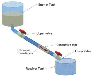
It was simulated the fluid transport crossing the pipeline by building experimental equipment at laboratory scale. The equipment uses a top tank where the drilling mud is stored, two valves (upper and Lower) to control the mud flow, a diagonal pipeline and a lower-Level tank (See Figure 5). The experimental equipment was built in the laboratory and all the experiments were performed using this experiment design.

Figure 5 Equipment design used in all experiments. All equipment parts were built in the Geomechanics laboratory at ICP (Colombia), where the tests were conducted.
The transducers were located on the pipe, one acts as an emitter and the others are receivers. The distance between transducers depends on the pipeline diameter and length. We performed several tests in order to find the best location for the transducers, so that the signal had the best signal to noise ratio.
4. RESULTS
A series of experiments were performed in order to obtain the model for the volumetric flow of rock as a function of the change in frequency detected at the receiver. For all the experiments, the source had a known natural oscillation frequency and the acquisition system recorded acoustical signals automatically. The acquisition system started receiving signals when the flow began. Once the mixture flowed through the pipeline, the system detected a change in the maximum frequency at the receiver and it gave an estimate of the volumetric flow of the rock-mud mixture.
The experiments were performed for the sizes and concentration of rock proposed in Table 1. Signals were collected and their frequency was estimated. For each experiment, the amount of cavings (in grams) was also measured along with the travel time through the pipeline. Two different models were obtained: one for a small cavings size and one for a large cavings size. Figure 6 depicts the data collected, as well as the proposed model for both sizes of cavings. The models relate the estimated frequency with the quantity in grams, and concentration of the rock in the mud-rock mixture. The model for small caving sizes follows an exponential behavior with the fastest change rate. On the other hand, for the larger size of cavings, the exponential model has the slowest change rate.
Once the model was built by running several experiments with different amounts of cavings and cuttings, the model was validated with a set of new experiments. These experiments used different concentration of rocks from both groups of sizes. Before inserting the rock into the drilling mud, the mass of rock was measured with a scale and the concentration of rock in the mixture was calculated The results from validation tests are recorded in Table 2.
Table 2 Input and experimental data used to validate the model proposed.
| Input Data | Experimental Data | Relative Error | ||||
| Cone. (%) | Mass (g) | Cone. (%) | Mass (g) | Cone. (%) | Mass (g) | |
| 0.320 | 90.000 | 0.293 | 82.123 | 8.437 | 8.752 | |
| 0.390 | 109.000 | 0.349 | 99.000 | 10.512 | 9.174 | |
| 0.680 | 190.000 | 0.844 | 236.294 | 24.117 | 24.365 | |
| 0.750 | 210.000 | 0.724 | 202.756 | 3.466 | 3.449 | |
| 1.095 | 306.000 | 1.476 | 413.510 | 34.794 | 35.133 | |
As stated before, Table 2 contains the information from validation data; the first two columns report input data, which correspond to the measured mass obtained with the scale. Columns three and four are called "experimental data," corresponding to the modeled results. Finally, in last two columns of Table 2, the relative error (as a percentage (%)) is computed as a comparison measure, between measurement by scale and the model.
5. RESULTS ANALYSIS
As shown in the experiment results, there is an exponential relationship between the frequency change of the emitted and received acoustic signals, and the volumetric flow of cavings through the flow line. Thus, the frequency change varies depending on the rock size and concentration of rocks in the drilling mud passing through the flow line pipe.
The frequency change varies from 1100 to 1600 Hz for small rocks or cuttings; and from 1600 to 6800 Hz for cavings. The results obtained during experimentation show that when mud carries small rocks, the acoustic frequency of the received signals experiences rapid decay if only a few grams of rocks were changed. On the other hand, for large samples of cavings, a much slower decay in frequency was observed for the same change in mass, leading to a wider range of frequencies.
Additionally, the empirical model obtained with the experiments shows that there is a range in the frequency change (between 1800 and 2000 Hz) in which mass of rock can be miscalculated, because it indicates either a small concentration of large cavings or a large concentration of small cavings. Since it is important to determine the size of the rock crossing the pipe to detect the instability of the well, then this issue should be corrected by including some additional information on the signals received, such as amplitude.
CONCLUSIONS
The proposed method makes it possible to estimate the concentration of cavings in a mixture of mud-rock using the ultrasound Doppler effect. The method is suitable for real time applications while drilling, since it is non-invasive and the acquisition system is relatively simple.
In the experiments performed in the laboratory, large changes in frequency were observed when a concentration of large rock was crossing the pipeline, whereas small changes in frequency represent a higher amount of small rock crossing the pipeline. This behavior makes it possible to estimate not only the concentration of cavings but also their size.
The proposed empirical models relate the signal's change in frequency (between the emitter and the receiver signals) with the amount of cavings that are passing through a certain cross-section in time.
The models were found to behave exponentially with different rates of increase for different sizes of cavings, and seem to be more suitable for small concentration of rocks because low relative error values were obtained.


