Introduction
Machines and parts have been built using traditional (subtractive) processes such as welding, bending, soldering, and machining for decades 1,2. This process manufactures products and parts by removing material from material blocks to achieve the desired shape. Machining has helped humans create many things 3. However, there are some limitations that restrict its performance and efficiency. The manufacturing of complex parts and devices is challenging, time-consuming, energy-intensive, imprecise, and precise, costly, and wasteful of materials. The introduction of unconventional machining methods, such as electrical discharge machining and chemical machining, and the utilization of computer technology, help mitigate these shortcomings 1), (4.
Today, additive manufacturing is the process of creating an object by adding a layer of material to form that object 5-8. An example of additive manufacturing is a three-dimensional (3D) printing process, a method of producing 3D objects from a digital file 1,9. 3D printing consists of computer-aided design (CAD), material addition, and the machine 10. The printing process begins with the design of a digital object using computer-aided design (CAD) software or by capturing the object with a 3D scanner. Popular software options include SolidWorks, AutoCAD, Inventor, and more 11-13. he CAD design defines the geometry of the object 1,14, and the quality of the CAD design significantly affects the production and accuracy of the printer 3. CAD designs are prepared for printing by slicing the design into a series of horizontal layers using slicing software that is loaded into the 3D printer. The slicing software also generates G-codes for each layer to be cut and generates a special toolpath command for the extruder head that applies each layer of material 8,15,16. The American Society for Additive Manufacturing has established standards that categorize additive manufacturing processes into seven areas: material extrusion, directed energy deposition, photopolymerization, binder jetting, sheet lamination, material jetting, and powder bed fusion 17.
Polylactic acid (PLA) is one of the thermoplastic polymers commonly used in 3D printing technology due to its excellent processability, biocompatibility, and biodegradability 18. Despite these advantages, the mechanical properties of PLA require additional improvements. Various methods, such as blending, have been employed to address these issues 19, copolymerization 20, surface modification 21) and the incorporation of fillers into the PLA matrix 22, with the latter showing great promise in enhancing PLA performance 23.
An Unmanned Aerial Vehicle (UAV) is an aircraft that operates without the physical presence of a pilot on board, instead controlled from a station or operated independently according to a flight program using devices and sensors from the Global Positioning System (GPS) installed on the UAV 24. UAVs have been developed for both military and civilian missions, such as reconnaissance, assault missions, rescue missions, wildlife observation, border patrols, firefighting, agricultural surveillance, or gathering meteorological data. Composite materials, lightweight metal alloys, foam, and wood are used in the manufacturing of drones 25.
In the last decade, the UAV market has undergone significant growth, with leading companies like DJI achieving significant milestones in the development of aerial vehicles, such as the F330 and F450 models. These have been recognized for their efficiency and global market presence since 2012, undoubtedly establishing an important benchmark in the unmanned aerial vehicle industry 26.
To date, the construction of these aircraft has undergone constant improvements due to the need to increase flight autonomy 27. The most used materials in the unmanned aircraft industry are fiberglass, carbon fiber, and aluminum due to their density, high strength, rigidity, and low weight 28. These composite materials offer a higher strength-to-weight ratio compared to pure materials, making them ideal for UAVs by allowing a greater payload capacity or increased flight autonomy with less energy consumption. Additionally, their resistance to corrosion and fatigue is superior, prolonging the lifespan of the UAV. Finally, the flexibility in design and the ability to be molded into complex shapes allow for more efficient aerodynamics, optimizing the performance of the unmanned aerial vehicle 29) (30.
As a result, the technology of Fused Deposition Modeling (FDM), known as 3D printing, is a promising method for UAV construction because it allows the production of three-dimensional objects using a technological device by placing several two-dimensional layers of a specific material on top of each other 31. It can be used to create all kinds of parts, from prototypes and simple components to highly technical end products, with the advantage that when a part is damaged, there's no need to purchase the entire assembly. It has become an economically viable technology today.
This technology incorporates polylactic acid (PLA), a thermoplastic biopolymer that has attracted the interest of researchers, producers, and processors. Aside from its biodegradability, it has been found to be a strong competitor against other petrochemical-based plastics due to its broad and unusual range of properties, from the amorphous state to the crystalline state 32. It's a practical and cost-effective method for manufacturing UAVs due to its ease in obtaining complex and lightweight geometries.
Moreover, PLA stands out as a viable choice for constructing the chassis of a UAV for several specific reasons. Its strength, although lower compared to some composite materials, is sufficient for moderate-weight applications, especially when considering factors like strength-to-weight ratio and ease of acquisition. Its lightweight nature is crucial, significantly contributing to reducing the total weight of the UAV, thus enhancing its energy efficiency and payload capacity.
Stress analysis is fundamental when choosing a material for the UAV chassis. Although PLA may have certain limitations in tensile strength and at high temperatures, its behavior under specific loads and rigidity are suitable for applications prioritizing weight reduction without compromising necessary structural integrity. Additionally, its ease of 3D printing facilitates the manufacturing of complex and customized designs, enabling the optimization of geometry to distribute stresses and enhance its strength 33.
In the department of Córdoba, the use of UAVs can have a significant influence due to the diversity of activities carried out in the region. In an agricultural region like Córdoba, UAVs are used to monitor crops, identify areas of plant stress, map terrains, and conduct soil analyses. This allows for more precise resource management, improves productivity, and assists farmers in making data-driven decisions. Similarly, UAVs can be useful in surveillance operations for public security, border control, and monitoring remote areas, which can be crucial in an extensive region like Córdoba. Lastly, Córdoba hosts a diversity of ecosystems that can be studied using UAVs. These devices enable the monitoring of biodiversity, assessment of environmental changes, and tracking of flora and fauna in a more efficient and less intrusive manner. All of this allows for a more efficient and detailed data collection in a region with varied geographical and environmental characteristics.
Given the above, it is crucial to understand that the uniqueness of our approach lies not in the novelty of the entire aerial vehicle design but rather in the specific innovation involving the evaluation of polylactic acid (PLA) use in 3D printing for the construction of an unmanned aerial vehicle structure. This present work focuses on applying this innovative material in the design and construction of a UAV structure, exploring its implications in terms of strength, weight, and sustainability. The intention of this study is not so much to develop a new UAV model but rather to analyze the viability and potential benefits of a specific material in its construction, thus contributing to the advancement of aerospace technology. Furthermore, the use of PLA in 3D printing for UAV structure manufacturing presents a pioneering approach that brings novelty to the current technological landscape, especially in terms of material sustainability and versatility. This approach represents a significant step toward exploring new materials for continuous improvement in the field of aerospace engineering. With the aim of contributing to the state of the art in this field, our research focuses on establishing a solid foundation for future advancements and developments in the unmanned aerial vehicle industry, promoting innovation and technological progress.
Methodology
A four-rotor unmanned aerial vehicle was designed and built, featuring a chassis structure supporting the electromechanical system and components used for measuring parameters of interest. The methodology employed for the UAV chassis utilized a MAKE R Tairona Prusa A-360W-12 printer. Repetier-Host software was used for design, allowing optimal precision in prototype creation. The MAKE R brand material of 3 mm, with a printing temperature ranging between 190-230°C, was specifically chosen to ensure the necessary strength and durability for the UAV chassis. Besides stress analysis, detailed prototype development was undertaken to optimize its performance under real conditions.
The UAV comprises four arms, an 'X' configuration of propellers, a body, and upper and lower covers. Various parameters were taken into account for designing the different UAV components, as described in Table 1.
Table 1 Initial Parameters for UAV Design
| PARAMETER | VALUE |
|---|---|
| Wheelbase Distance | 450mm |
| Estimated Flight Time | 20 mín. |
| Mass | <1,7 kg |
| Maximum Altitude | 50 m |
| Operating Range | < 1000 m |
| Rotors | 1000 kV |
| Takeoff Speed | 11 m/s |
| Wind Speed | 3,2 m/s |
| Propeller Configuration | 2 Blades |
| Batery | 5, Ah-11.1 V |
With these parameters, preliminary calculations were conducted to determine the power of the motors and the definition of the propellers, resulting in 4 brushless motors of A2212 reference, each with 1000KV, a maximum power of 150W, and a nominal operating voltage of 11.1V. The SIMONEK speed controllers were used, with each one placed on one of the arms of the UAV. Inside the body, the flight control unit APM2.8, GPS, PMS 1003 particulate matter sensors, DHT 22 for measuring temperature and relative humidity, MQ-7 for carbon monoxide, and a 5Ah battery were installed. The relevance of sensors in studying the chassis of a drone made from PLA material is crucial to evaluate its performance in diverse conditions. These sensors enable the collection of data on environmental factors, mechanical stresses, and other parameters that can affect the chassis' behavior.
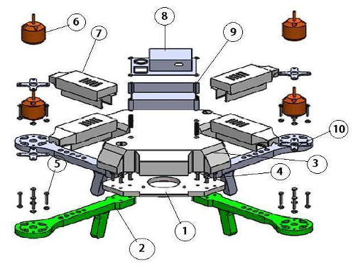
The material primarily used for the structural system of the UAV was PLA, with smaller amounts of aluminum and low-carbon steel used for fastening components with bolts. The body (1), arms (2), upper casing (3), speed controller cover (7), sensor box cover (8), and sensor box (9) were made from PLA. The bolted joint of the central chassis arm (4) and the bolted joint of the rotor arm (5) were constructed from low-carbon steel, while the motor mount was made from aluminum, as shown in Figure 1.
Power and Force Calculation
The maximum power required by the UAV motors is determined when the takeoff speed is equal to 0, according to Equation 1:
Where: 𝑃𝑜 = Power, T= Lift force, 𝑣𝑧 = Vertical velocity, 𝑣𝑖 = Induced velocity.
This calculation was performed considering the induced velocity and lift force determined by equations 2 and 3.
Where: 𝑣𝑖 = Induced velocity, 𝑝= Ellipse steps, and RPM is the rotor's revolutions per minute.
The lift force is equal to the weight
Where: 𝑇= Lift force, W = Weight, m= mass and 𝑔= gravity.
Furthermore, the force to which the 4 arms of the UAV are subjected is determined using equation 4.
Where: F= Force exerted by the motors on the arms, 𝑃𝑜= Power, 𝑣= takeoff speed.
Structural Analysis
To determine the chassis design, a structural analysis simulation was performed using the finite element method in SolidWorks software. The goal was to identify points where stresses are maximum and minimum in order to establish the construction characteristics of the parts. This analysis also allowed for the verification of the mechanical strength of the elements that make up the UAV's structure when subjected to lift force, ensuring that it will withstand various loading conditions. In the meshing process, parameters ensuring good mesh quality were taken into account according to finite element theory, as shown in Table 2.
Table 2 Meshing Parameters
| Parameters for Mesh Quality | |
|---|---|
| Element Geometry | Tetrahedral |
| Aspect Ratio of Elements | <3 |
| Jacobean Points | 4 points located at the nodes |
After obtaining the mesh of the structure, a structural analysis was conducted again, and Von Mises stresses in the central structure and arms were calculated, taking into account the mechanical properties of PLA as described in Table 3. This information was compared with the design's safety factor, ensuring that the stress levels experienced by the structural element were lower than the yield stress (𝜎𝑓).
Table 3 Mechanical Properties of Polylactic Acid Processed by Fused Deposition Modeling (FDM).
| Mechanical Properties | Typical Value | Measurement |
|---|---|---|
| Elastic Modulus | 3,5 | GPa |
| Tensile Strength | 49,5 | MPa |
| Flexural Strength | 80 | MPa |
| Flexural Modulus | 4 | GPa |
| Hardness | 83 | Shore D |
| Glass Transition Temperature | 65 | °C |
| Melting Temperature | 160 | °C |
Source: 34
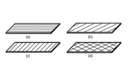
According to the infill orientations and mechanical properties specified in Table 3, a 0° angle was used, as shown in Figure 2. This direction is recommended for better mechanical properties, as maximum tensile strength results in parts oriented in this way, while maximum bending stresses would be in the same direction as the filament, with the opposite being the case for a 90° orientation 35.
Aerodynamic Analysis
An aerodynamic analysis was conducted for the assembly of parts: upper casing, body, arms, lower casing, and speed controller casing to determine the drag coefficient and the forces involved due to drag and lift caused by the vehicle in the air using ANSYS software version 17,1. For the aerodynamic design of a drone manufactured with PLA, several criteria need to be considered, such as the overall shape of the drone, which significantly impacts its aerodynamics. A design that reduces air resistance and allows stable flight within established limits of tilt, speed, and dimensions was taken into account. Additionally, the distribution of mass and placement of components like the battery, motors, and electronics also affect aerodynamics. A balanced design contributes to the stability and maneuverability of the drone. The drone's resistance to wind is crucial, especially considering the specified maximum wind speed. Ensuring that the design minimizes resistance and maintains stability even in windy conditions was a priority. For this analysis, the following input parameters were considered: maximum tilt angle of 35°, flight velocity of 5 m/s to 8 m/s, maximum wind speed of 3,2 m/s, and boundary conditions of 2440 x 2140 x 1590 mm with a wind density of 1,225 kg/m3.
Additionally, the prototype's weight is a crucial factor considered in all calculations and analyses during development. The PLA material used for the drone chassis directly influences its weight, impacting aspects such as structural resistance, flight capacity, and energy efficiency. Therefore, resistance calculations, flight simulations, and stress analyses have considered the prototype's specific weight. Understanding how this weight influences maneuverability, durability, and overall drone performance is fundamental. Furthermore, in the chassis design, a balance between strength and lightness has been sought to maximize efficiency without compromising structural integrity. Hence, weight has been a fundamental parameter at all stages of prototype development.
After conducting the aerodynamic analysis and obtaining the drag coefficient, the force exerted by the wind on the UAV was calculated using Equation 5. It was then verified whether the UAV can fly under these conditions by comparing it with the maximum horizontal flight force, considering that the drag force must be less than the maximum horizontal flight force.
Where: 𝐹𝑟= Drag Force, 𝐶𝑑= Drag Coefficient, 𝜌 = Air Density, 𝑣 = Wind Velocity.
Once the drag force is calculated, the maximum horizontal flight force delivered by the rotors is also determined using Equation 6.
Where: 𝑃𝑜= Flight Power, 𝑉𝑣= Flight Speed.
Finally, all the parts were assembled, and the UAV was constructed. To validate its performance, flight tests were conducted, and the hover time, altitude, and flight time were measured.
Results and discussion
Calculation of power and force
An induced velocity of 21.14 m/s was obtained, which is the speed at which the air is induced or diverted downwards by the UAV's blades to generate lift. The lift force was measured at 16.667 N, indicating the upward force generated by the UAV to counteract gravity. This determined a maximum power requirement for the motors of 536 W. This power is necessary to maintain the UAV in flight, overcome aerodynamic resistance, and generate the necessary force for lift. Additionally, a force exerted by the motors on the arms of 13.63 N was calculated, which is related to thrust generation to counteract aerodynamic resistance or might be the force exerted on the UAV structure, as shown in Table 4. The relationship between lift force and the power required for the motors is crucial in aircraft design. Greater weight or lift force will require more power to sustain flight.
Structural Analysis
A mesh quality within the accepted parameter range was obtained. In terms of aspect ratio, there was a 0,1% of elements with a coefficient greater than 3, which is consistent for conducting static simulations. The total load was 30,21 N evenly distributed across the 4 arms, with a safety factor of 3,24.
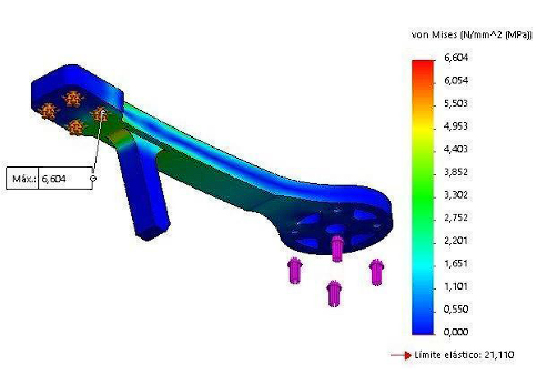
The results of the structural analysis show that the minimum stresses are located in the chassis arms, while the maximum stresses are found at the chassis attachment point with a value of 6,604 MPa, well below the elastic limit of 21,110 MPa. These parameters meet the design criteria, as the maximum Von Mises stress in the structure remains below the elastic limit, as shown in Figure 3.
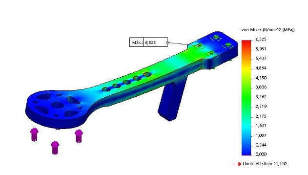
In order to reduce the weight and ensure the flight autonomy of the UAV, five holes with a diameter of 6mm and a spacing of 10 mm were made in each arm, as shown in Figure 4.
After the perforation, a safety factor of 3.23 was achieved.
Aerodynamic Analysis
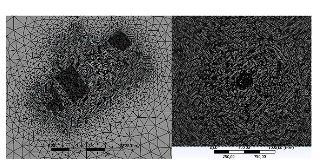
The mesh quality conditions yielded acceptable results as the values fall within the appropriate range obtained in ANSYS 2017, as shown in Figure 5. A total of 332.404 nodes and 1.782.248 elements were obtained.
The coefficients of drag and lift are key parameters in aircraft design. These values vary with the angle of attack and speed. Generally, the lift coefficient is expected to increase with the angle of attack, which is evident in the provided data. Coefficients of drag and lift were obtained for angles of attack of 0° and 35°, and speeds of 5 and 8,2 m/s, resulting in values of 0,25; 0,32; 0,25; and 0,32, respectively. It is noticeable that the coefficient values vary between the two speeds. For instance, at a speed of 5 m/s, both the coefficients of drag and lift are 0,25 at 0° and 0,32 at 35°. However, at 8,2 m/s, the values are consistent with those obtained at 35°, indicating that at higher speeds, the UAV operates more efficiently in terms of lift and drag. While these data might not suffice for a detailed design analysis, they offer an initial perspective. In an ideal design, a high lift coefficient with a low drag coefficient would be sought to achieve better efficiency. The provided data show a trade-off, as there is an increase in the lift coefficient with the angle of attack, but there is also an increase in the drag coefficient.
A drag force of:
𝐹𝑟=1𝑁
And flight power of:
𝐹𝑥=108.44𝑁
As can be seen, the lift force is much greater than the drag force; therefore, it can be said that the flight of the UAV will not be affected by the wind speeds present in the area. On the other hand, these forces reduce flight autonomy.
Likewise, a significantly greater lift force than drag force can indicate that the UAV design is more efficient. This suggests that the UAV might be capable of flying at higher speeds or consuming less energy to sustain its flight, resulting in better overall performance. It can also allow the UAV to carry a heavier payload, which can be beneficial for missions requiring additional equipment, sensors, or specific payloads.
Moreover, a high ratio between lift force and drag force can imply that the UAV consumes less energy to maintain flight, potentially extending its flight time and increasing its autonomy.
During the assembly process, no issues of any kind were encountered, and all the structures were perfectly fitted together, as shown in Figure 6.
The UAV met all validation parameters, achieving a flight altitude of 48 m and an autonomy of 17 minutes, as shown in Figure 7.
Now, considering a study conducted by 36, the structural analysis revealed that the maximum Von Mises stress found where the chassis is attached was 3.79 MPa. In comparison with the result of the present study, this showed an increase of 57%. This suggests that as we stand at the forefront of the aerospace industry, where weight reduction is critical, a higher Von Mises stress might allow for a reduction in material without compromising structural integrity. Moreover, this indicates that the UAV has a greater deformation capacity without breaking, which could be useful in situations such as impact damping, signaling an improvement in the proposed design and the material used for manufacturing.
Similarly, the flight time in the present study saw an increase of 59% compared to 36, all due to the fact that PLA is known to be lighter compared to other materials used in 3D printing, such as ABS or nylon. The reduction in weight can contribute to a lighter payload for the UAV, which in turn can extend the flight time. Less weight means the UAV requires less energy to stay in the air, resulting in higher energy efficiency and extended flight. Additionally, the design of the 3D-printed parts with PLA improved the UAV's aerodynamics, which can contribute to more efficient flight. Reduced air resistance could translate to a longer flight time.
Conclusions
The advancements in additive manufacturing technologies have generated considerable interest in the production of unmanned aerial vehicles. Additive Manufacturing (AM) provides designers with the capability to create intricate designs that are challenging to produce using traditional methods. It doesn't necessitate casting materials or tools, thus saving time, costs, and effort. Besides streamlining the manufacturing and assembly process, composite manufacturing has the advantage of reducing tool and material expenses. Flight models designed and manufactured show that the UAV is constructed almost entirely using Fused Deposition Modeling (FDM) technology and can fly and operate with excellent aerodynamics and maneuverability.
The data obtained from the analysis showed that the UAV was designed based on the applied loads. The UAV was produced using polylactic acid (PLA). During the ground and flight testing of the UAV, no damages occurred, and the PLA parts produced withstood the applied loads. This is why the use of PLA in unmanned aerial vehicles is more efficient, faster, and cost-effective compared to other materials. The results of the structural analysis show that the value of the applied load is still below the tensile strength of the material, and the structure has a safety margin of 3.23 under the maximum lift condition applied to the UAV.
This is why additive manufacturing, particularly 3D printing, has become an area of extraordinary potential in creating diverse geometries that surpass conventional imagination. Polylactic acid (PLA), as a material used in this process, has shown unique versatility in creating structures and components, especially in the unmanned aerial vehicle industry. While established scientific and technological foundations are crucial, true innovation and progress occur when new applications within this technology are explored and developed.
Additive manufacturing with PLA not only allows for the replication of existing designs but also opens the doors to exploring previously unattainable geometries and structures. By introducing original applications in UAV construction, it's possible to not only optimize designs and components but also drive progress at the forefront of science and engineering.
Therefore, this work not only focused on implementing already known techniques but aimed to go beyond by exploring and presenting original and innovative applications of polylactic acid in 3D printing for UAV construction. This initiative sought not only to demonstrate the feasibility of this material in a specific context but also to stimulate discussion and innovation within the scientific and technological community. With all of this, this work not only supports established practices but also advocates the need to explore new applications and geometries in additive manufacturing with polylactic acid. The ability to advance at the frontier of science and technology lies in the originality and creativity in applying these concepts in uncharted contexts.


