Introduction
In the early days of AC power generation, the stator windings of the synchronous generators were provided with solid copper bars and despite the increase of copper cross section, the current could not be increased to the same extent, due to the stray magnetic fields that produce eddy currents which cause the displacement of the density of currents in the bar. Therefore, the cross section of copper was not used by all the current intrinsic in a conductor. Thus, when a designer wanted to increase the efficiency, the way commonly used was the use of a disproportionately amount of cooper, nonetheless, these machines often turned too hot, to such an extent that, it was hardly possible to build generators with more than 10 to 20 MW of power. 1
By 1912, Ludwig Roebel present the innovation of the transposition of sub conductors 2, which make possible to build larger electric motors and generators, whose power range exceeds 75 MW, with some exceptions, depending on the discretion of the designer. This type of armature winding configuration is called Roebel-type bars, where the sub conductors, wires or plates are transposed in the slot, that is, in the active part of the coil in multiples of 180° and are welded in the terminals of the coil. This type of distribution that reduces the power losses in the stator, brings up a better operation point for the generator and increases the efficiency by preventing the overheating of the stator winding, that increases the useful expected life of the machine.
The methodology presented by Roebel has been introduced by different authors of books and papers about the practical sizing of electric machines like Juan Corrales Martin, Karl Vogt, Aleksandr Abramov, J. Pyrhönen, T. Jokinen, and V. Hrabovcová; in present paper a critical comparison between the procedures defined by these authors is done by using one study case of the generator power unit number one of the hydraulic power plant of SALVAJINA in Colombia.
The paper is organized in four main sections, Methodology: That present the method used to compare the different procedures defined in the literature, Results: That present the results of the comparative analysis, Discussion: Where a brief discussion about the future appliances of the results is done and finally the conclusions about the application of the method used.
Methodology
At the first a complete description of the Roebel transposition principles is stablished, the description of the physical phenomena associated with the presence of Eddy currents in an unstrained bar for a conventional synchronous generator is compared with the electromagnetic field in a strained bar. With the help of the software COMSOL, a visualization of the phenomena is shown. Then a compilation of the literature available from different authors to implement the Robel transposition in the sizing of a Roebel-type bar are applied to obtain information and parameters that are compared with a real bar provided by the plant.
Roebel transposition
When AC current circulates through the conductors of the stator winding, an AC magnetic field encloses the conductors and crosses the slot and consequently a magnetic flux density (B) that links the slot is induced. This flux density increases from 0, at the bottom of the slot, up to a maximum value in the top of the slot. By following the Lenz law, this changing flux density induces an electromotive force (EMF) opposed to the circulating currents, that generates an opposite current (Eddy currents) that forces the current density to the outer edges of the conductor (Skin effect). This phenomenon forces the concentration of the current density in the areas where the self-induction becomes minimum, in consequence the electric current isn´t be uniformly distributed on the surface of the conductor, causing that a significate part of the transversal section of the conductor becomes unused. The reduction of the transversal section generates an increase of the electric resistance and the power losses that can be separated into eddy currents losses and circulating currents losses 3.
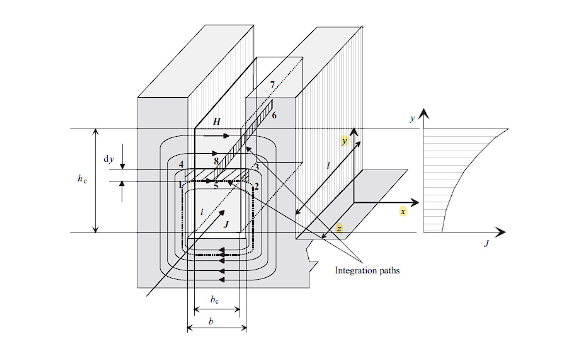
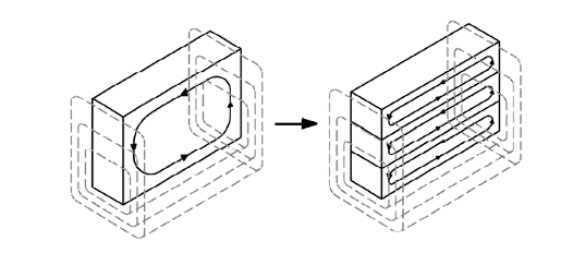
Thus, current displacement is a specific case of the skin effect, which depends on the arrangement of the circuit followed by the self-inductive flux. However, if the conductor is housed within a stator slot, the current distributions are significantly different due to the surrounding ferromagnetic material. In this scenario, there is a pronounced concentration of magnetic field at the top of the slot. Consequently, the skin effect causes the current to flow toward the upper part of the conductor, driven by a higher self-induced electromotive force (EMF) that prevents current circulation in the lower part of the conductor. As a result, the magnetic field in the region where the flux links with part of the ferromagnetic core becomes negligible. The magnetic field contribution from the upper part of the conductor dominates, as depicted in Figure 1. Therefore, the current concentration in a non-transposed bar is non-uniform and increases with the slot height.
The leakage flux linking the slot, induces an E.M.F in the conductors that is greater on the top of the conductor than on the bottom; the induced potential difference cause circulating Foucault currents (Eddy currents), when the induced potential difference increases the Eddy currents increases. Since the conductor is separated into several strands insulated one from each other as shown in Figure 2, the difference between the flux links from top to bottom on each string in considerably lower, thus a smaller potential difference is induced and reduced eddy currents are present, and then the total copper losses are reduced.
Source: 3.
Figure 2 Potential difference compared between an unstrained conductor Vs a strained conductor.
Now, if the conductor is composed of several insulated strands, the ends of the strands are welded, and since there is a potential difference between these subconductores due to the magnetic flux density of the slot, circulating currents will flow inside the coil. These currents are caused by differences of self-induced electromotive force (EMF) produced by the uneven distribution of the field within the slot. This results in additional losses, which reduce the efficiency of the machine and heat the winding.
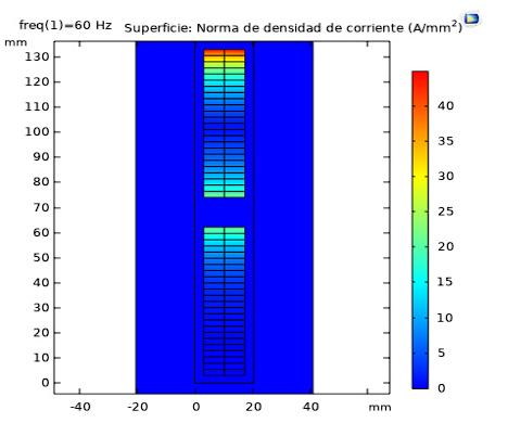
The non-uniform current distribution caused by the self-inductive effect of the current in the same conductor is also due to the inductive action of other conductors whenever the field from these conductors passes through the conductor in question. An example of the current distributions of two superimposed bars is shown in Figure 3. In this 2D steady-state COMSOL Multiphysics simulation, with a mesh quality of 0.89 for 9346 elements, it can be observed that the current concentration in a non-transposed bar is non-uniform and increases with height. The effect observed at the base of the top bar is due to the presence of dispersion flux linkages produced by the current concentration of the bottom bar, in addition to the so-called compensating currents that exist due to the unequal dispersion flux produced by the top and bottom bars, whenever they are connected in parallel, at points outside of them. The compensating currents do not close exclusively within the conductor, but also extend through the coil heads, whose resistance is incorporated to reduce the compensating currents.
Source: 5
Figure 3 Transversal section of a strained bar without transposition simulated in COMSOL MULTIPHYSICS.
Despite the division of the conductor into sub conductors, the distribution of current densities is not uniform. This is because the flux closes asymmetrically towards the base of the teeth, indicating that the conductors at the bottom of the slot have a higher inductive reactance than those at the top of the slot, causing the current to concentrate at the top of the slot. In the absence of effective methods to mitigate the consequences of current displacement in the machine, the Roebel system of constructing the bar from several insulated and interlaced subconductores helps to balance the effects of the scattered magnetic fields in the bar, all parallel sub conductors induce the same electromotive forces, and the entire copper cross-section is used almost uniformly. This is due to the constant change between the sub conductors, which minimizes the skin effect considerably. Consequently, the sums of the partial fluxes of the integration paths that cause Foucault currents are eliminated, and by obtaining the same average electromotive force (EMF) inductions, circulating currents are eliminated. However, the skin effect persists in the sub conductors, albeit to a lesser extent. This can be further reduced by employing sub conductors with as small a cross-sectional area as possible. These modifications are subject to dimensioning calculations. These sub conductors must generally be welded at the end of each slot, in the coil head or end part, front and rear. In some cases, they must extend through all or at least several slots before they can be connected in parallel. Otherwise, internal currents would also be generated.
The Roebel system or Roebel transposition, is used in large generators of up to 2200 MW, each coil is formed by thin copper wires or strips insulated from each other in two columns 6. These columns are braided and taped with a layer of insulation, typically, this type of winding consists of a single effective turn per coil. In other words, it is formed by half-coils, with half of a coil inserted into one slot and the other half into another slot, which is much easier than placing both sides of the coil into two different slots at the same time, once the half-coils are inserted, the ends are connected, and the coil is completed. The sub conductors are transposed in the slot area, that is, in the active part of the coil in multiples of 180° 7, this winding configuration is one of the most effective ways to limit the skin effect, which causes current displacement, and consequently reduces additional copper losses that lead to lower efficiency and, above all, overheating of the stator winding, therefore can lead to insulation damage that reduces the machine's lifespan, not to mention the significant economic losses caused by this phenomenon.
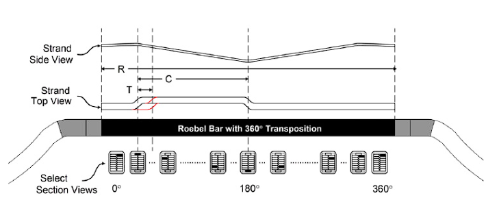
Figure 4 illustrates the Roebel transposition, which is performed only in the slotted area. In this case, a 360° transposition ensures that the sub conductors occupy all possible positions within the same bar. This means that a subconductor initially located in the upper-left position is shifted to the next lower-left position and continues in this manner until it reaches its original position. As a result, the total induced voltage in this strand will be the same as that of the other transposed strands, and the current densities will be approximately equal.
Source: 3.
Figure 4 Position of the transposed strand along the Roebel transposition at 180° and 360°.
Since there are no potential differences, the ends of these strands can be connected without causing circulating currents. There are different methods for transposing sub conductors, but the most common is to shift them from right to left and top to bottom.
Research methodologies
Once the information, parameters, and procedures from the consulted bibliography have been collected, the different procedures that allow the sizing of a Roebel-type bar are applied. The results obtained in each procedure are compared with the real bar provided by the blueprints to ensure an acceptable margin of error, according to 8, for the design of large synchronous machines, calculation errors should be within 10%, Table 6. Subsequently, a compilation of the applied methodologies is carried out to establish a methodology that allows the sizing of a Roebel-type bar that can be generalized to other generators in a clearer and more methodical way. Therefore, the sequence of the investigated methodologies is specified and proposed as follows:
Note: The nomenclature of the methodologies is different; therefore, the sequence is expressed using the names of the parameters.
A. Methodology defined by Juan Corrales Martin.
The initial steps will be detailed using the method of 9 (pages 162-167 of 10) as a guide for following the other authors.
1. Compile the minimum required information, which is the basic data presented in Table 1.
Table 1 Initial data.
| Parameter | Symbol | Value | Units |
|---|---|---|---|
| Current per phase | 𝐼𝑓 | 2615 | A |
| Conductors per slot | 𝑍𝑛 | 2 | - |
| Number of slots | n | 300 | - |
| Air gap diameter | D | 7130 | mm |
| Rated speed | N | 180 | r/m |
| Active core length | 𝐿h | 1270 | mm |
2. Calculate the current density of the conductor.
For conductor sizing, it is initially necessary to determine the conductor cross-sectional area, Eq. 4, which depends on the allowable current density, ∆, for which it has:
Where:
𝑞: is the specific linear load.
𝑞Δ: allowable 𝑞Δ variance related to conductor heating.
To determine the current density, the following parameters are required:
2.1. Calculate the peripheral speed of the generator.
To determine the allowable current density, it is necessary to find the allowable variation of q∆/∆θ on the surface of the coil heads, which is determined by the peripheral speed 𝑣 using the following equation, where N is the rotational speed of the machine in (rpm):
2.2. Find the variation of 𝑞∆/∆𝜃 admissible according to 9.
Given that the machine under study belongs to a hydroelectric power plant and operates at low speed 𝑣=66,935 𝑚/𝑠, the allowable 𝑞∆/∆𝜃 variation is defined according to reference 10, which presents the values of 𝑞∆ that can be adopted for each degree Celsius of temperature rise in the coil heads, as follows:
2.3. Find the allowable 𝑞Δ variance according to 9.
The current density is also related to conductor heating. In this regard, the estimated allowable temperature variation in the coil heads, considering that the stator winding in operation is at 100 °C, with class F insulation (where the maximum allowable operating temperature is 155 °C), Therefore, for an allowable temperature increase of ∆𝜃= 45°𝐶 in the coil heads, the following relationship holds:
2.4. Calculate the specific linear load.
Likewise, the specific linear load 𝑞 must be calculated using the following equation:
3. Calculate the cross section of the conductor per phase.
Once the above parameters have been determined, the conductor cross-sectional area per phase 𝑆𝑓:
Where:
𝑆𝑓: is the cross section of the conductor per phase (mm2).
𝐼𝑓, is the current per phase (A).
∆, is the allowable current density (A/mm2).
4. Determine the main dimensions of the bar.
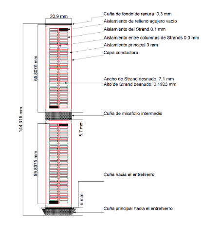
The main dimensions of the bar are determined and shown in Figure 5.
4.1. Calculate the width of the slot.
The slot width 𝑎 is determined as the difference between the tooth pitch 𝜏𝛿 and the tooth thickness 𝑡𝑜:
Where:
𝜏𝛿: is the maximum tooth pitch.
𝑡𝑜: is the maximum tooth thickness.
4.2. Define the main insulation thickness accordingly with the voltage level.
Where:
U: is the nominal machine voltage.
Main insulation thickness or also called intermediate micafoil wedge, adopted: 3 mm.
Note: The various slot sizing methodologies do not provide detailed information about the intermediate micafolio wedge, which is the insulating wedge separating the two bars when the winding is double layered. This is because these are confidential manufacturing parameters that are proprietary to the manufacturer.
4.3. Calculate the width of the bar only occupied by copper.
Where:
𝑎: is the slot width.
𝑡: is the main insulation.
C4.4. Calculate the width of the strand.
To determine the subconductor width, 𝑎1, it is necessary to define the width of the intermediate fabric, which is typically assumed to be between 0.3 mm and 0.6 mm according to industry standards. Thus, we have:
4.5. Define the insulation of the strand.
The thickness of the insulation between strands depends on the specific insulation material used by the manufacturer, it is typically 0,2𝑚𝑚.
4.6. Define the height of the intermediate micafoil wedge.
Intermediate micaf oil wedge adopted: 5,7 mm
4.7. Calculate the height of the strand.
The height of the strand, 𝑑𝐿, is determined using the minimum height criterion of constant current density and the integer number of wires in the depth of one turn.
4.8. Calculate the height of the conductor.
The height of the conductors in one layer, h𝑐𝑒
4.9. Calculate the height of the slot.
The total height of the slot h𝑡
4.10. Define the void fill insulation, considering the conventional insulation system.
4.11. Define the height of the main wedge towards the air gap.
4.12. Define the slot bottom wedge.
5. Additional dimensions are defined, and the main dimensions are readjusted for the final model.
B. Methodology defined by Karl Vogt.
The initial steps will be detailed using the method of 11 (pages 168 - 174 of 10) as a guide.
1. Compile the minimum required information, which is the basic data presented in Table 2.
Table 2 Initial data.
| Parameter | Symbol | Value | Units |
|---|---|---|---|
| Current per branch | 𝐼𝑧𝑤 | 2615 | A |
| Conductors per slot | 𝑍𝑛 | 2 | - |
| Number of slots | N | 300 | - |
| Air gap diameter | D | 7130 | mm |
| Active core length | 𝐿𝑖 | 1270 | mm |
2. Select the current density of the conductor, according to 11, Guideline values for current density.
3.Calculate the cross section of the conductor per phase.
To define the cross section of the conductors, the following parameters are necessary:
3.1. Calculate the peripheral load of the machine or linear load.
3.2. Determine the current per branch.
3.3. Take the current density of item 2 of this methodology.
4. Determine the main dimensions of the bar.
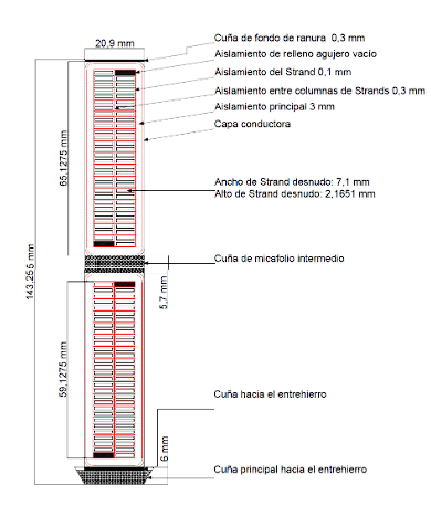
The main dimensions of the bar shown in a general manner in Figure 6 are determined.
4.1. Calculate the width of the slot, the procedure is the same according to item 4.1 of the Juan Corrales Martin methodology.
4.2. Determine the height of the slot.
4.3. Determine the height of the conductor.
The parameters of items 4.2, 4.3 of this methodology are initial approximation data.
4.4. Calculate the number of floors of the conductor.
4.5. Calculate the height of the strand.
4.1. Calculate the cross section of the strand.
4.1. Calculate the number of strands in the bar.
4.8. Define the main insulation.
4.9. Define the insulation between columns of strands.
4.10. Define the insulation of strands.
4.11. Define the height of the intermediate micafoil wedge.
4.12. Define empty hole fill insulation, considering conventional insulation system.
4.13. Define the height of the main wedge towards the air gap.
4.14. Define the height of the slot bottom wedge.
4.15. Calculate the total height of the slot.
5. Additional dimensions are defined, and the main dimensions are readjusted for the final model.
C. Methodology defined by Aleksandr Abramov.
The initial steps will be detailed using the method of 12 (pages 174 - 181 of 10) as a guide.
1. Compile the minimum required information, which is the basic data presented in Table 3.
Table 3 Initial data.
| Parameter | Symbol | Value | Units |
|---|---|---|---|
| Current per phase | 𝐼𝑛 | 5230 | A |
| Parallel branches | 𝑎1 | 2 | - |
| Number of slots | 𝑍1 | 300 | - |
| Conductors per slot | 𝑢𝑛1 | 2 | - |
| Slots per pole and phase | 𝑞1 | 2,5 | - |
| Air gap diameter | D | 7130 | mm |
| Active core length | 𝐿𝑖 | 1270 | mm |
| Pole pairs | 𝑝 | 20 | - |
| Specific electrical resistivity | 𝜌1 | 2,89·10-8 | Ωm |
| Loss magnification factor | 𝑘𝑟 | 1,32 | - |
| Peak sinusoidal air gap induction | 𝐵𝛿𝐻 | 1,15 | T |
| Peak sinusoidal tooth induction in no-load | 𝐵´𝑍1 | 1,96 | T |
| Relative shape factor | 𝐾𝑀 | 0,97 | - |
2. Calculate the current density of the conductor.
To calculate the current density of the conductor, the following parameters are necessary:
2.1. Calculate linear load.
2.2. Find the variation of ∆1𝐴 according to 12.
3. Calculate the cross section of the effective conductor.
4. Determine the main dimensions of the bar.
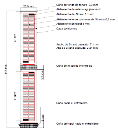
The main dimensions of the bar shown in a general manner in Figure 7 are determined.
4.1. Calculate the width of the slot, the procedure is the same according to item 4.1 of the Juan Corrales Martin methodology.
4.2. Calculate the width of the bar only occupied by copper.
4.1.1 Define the main insulation, according to 12.
4.1.2. Define the tolerance for punching and assembling of the core along the width of the slot, according to 12.
4.1.3. Calculate the width of the strand only occupied by copper.
4.3.1 Determine the thickness of the strand insulation, according to Table A1.3 12.
4.4. Select the height of the strand, according to Table A1.1 12.
4.5. Define the width of the strand, according to A1.1 12.
4.6. Determine the cross section of the strand, according to A1.1 12.
4.7. Recalculate the width of the slot.
4.8. Calculate the number of strands in a conductor.
4.9. Recalculate the cross section of the conductor.
4.10. Recalculate the current density of the conductor.
4.11. Calculate the height of the strand including its insulation.
4.12. Calculate the width of the strand including its insulation.
4.13. Calculate the total height of the insulated elementary strand of the bar.
4.14. Approximate the height of the main wedge towards the air gap.
4.15. Calculate the total height of the slot.
4.15.1. Define tolerance by punching and core assembling along slot height.
4.15.2. Calculate the height of the main wedge towards the air gap.
4.16. Define the insulation between columns of strands.
4.17. Define the height of the intermediate micafoil wedge.
4.18. Define empty hole fill insulation, taking into account conventional insulation system.
4.19. Define the slot bottom wedge.
5. Readjust the main dimensions for the final model.
6. Determine the average temperature of the slot insulation. Figure 7
Formulation of the methodology
The methodology is formulated by considering, in order, the calculations and procedures previously developed for the machine under study 5. Reference 10 presents the two application stages of the methodology, respectively, through diagrams that indicate the sequence in which the methodology should be implemented. The steps of the two mentioned stages are specified below:
1. Compilation of information and study of the of the machine´s operation under study.
1.1. Collect the necessary information of the machine such as dimensions, characteristics and tests performed.
Note: The compiled information presented in Tables 1, 2, and 3is required for implementing the methodology.
Note: It is worth mentioning that in high-power machines, such as the case study, it is not possible to stop their operation to perform measurements, as this would mean taking the generator offline, neglecting the energy demand, and consequently causing instability in the electrical system. Therefore, the information must be extracted from the generator's blueprints and tests.
1.2. Perform the study of the magnetomotive force (MMF) generated by the stator winding using the Piotr Wach methodology 13 or the Castro-Oslinger methodology 14.
1.3. Calculate the leakage reactance of the stator winding with the methodology presented by 1.
1.3.1. Calculate the slot leakage reactance.
1.3.2. Calculate the differential leakage reactance.
1.3.3. Calculate the leakage reactance of coil heads.
1.3.4. Calculate the total leakage reactance.
If the geometry and dimensions of the machine are available, it is recommended to validate the magnetic densities with the electromotive force (EMF).
2. Sizing of a Roebel type bar.
2.1. Compile the minimum required information, this is, the starting data given in item 1 of the proposed methodology.
2.2. Calculate the current density of the conductor, as shown in item 2 of the Juan Corrales Martin methodology, section A.
When determining the current density, the following parameters are necessary:
2.2.1. Calculate the peripheral speed of the machine.
2.2.2. Find the variation of 𝑞∆/∆𝜃 admissible.
2.2.3. Find the allowable 𝑞Δ variance.
2.2.4. Calculate the specific linear load.
2.2.5. Compare the current density obtained with the range of values provided in item 2 of the Karl Vogt methodology, section B.
2.3. Calculate the cross section of the conductor, as shown in item 3 of Aleksandr Abramov Methodology, section C.
2.4. Determine the main dimensions of the bar.
The main dimensions of the bar are determined in the following order:
2.4.1. Calculate the width of the slot, as in item 4.1 of the Juan Corrales Martin methodology, section A.
2.4.2. Calculate the width of the conductor, only copper, as in item 4.1 of section C.
2.4.2.1. Define the main insulation, as shown in item 4.2.1 of section C.
2.4.2.2. Define the tolerance for punching and core assembling along the width of the slot.
2.4.3. Calculate the width of the strand, like in item 4.3 of section C.
2.4.3.1. Define the insulation thickness of the strand, as shown in item 4.3.1 of section C.
2.4.4. Select the height of the strand, as shown in item 4.4 of section C.
2.4.4.1. Compare this parameter with the calculation shown in item 4.5 of section B.
2.4.5. Define the width of the strand, as shown in item 4.5 of section C.
2.4.6. Determine the cross section of the strand, as shown in item 4.6 of section C.
2.4.6.1. Compare this parameter with the calculation shown in item 4.6 of section B.
2.4.7. Recalculate the width of the slot, as referred in item 4.7 of section C.
2.4.8. Calculate the number of strands of a conductor, as shown in item 4.8 of section C.
2.4.8.1. Compare with the calculation of in item 4.7 of section B.
2.4.9. Recalculate the cross section of the conductor, as shown in item 4.9 of section C.
2.4.10. Recalculate the current density of the conductor, as shown in item 4.10 of section C.
2.4.11. Calculate the height of the strand including its insulation, as shown in item 4.11 of section C.
2.4.12. Calculate the width of the strand including its insulation, as shown in item 4.12 of section C.
2.4.13. Calculate the total height of the insulated elementary strands of a bar, as shown in item 4.13 of section C.
2.4.14. Calculate the total height of the slot, as shown in item 4.15 of section C.
2.4.14.1 Define tolerance by punching and core assembling along slot height.
2.4.14.2 Calculate the height of the main wedge towards the air gap, as shown in item 4.14 of section C.
2.4.15. Define the insulation between columns of strands, as shown in item 4.16 of section C.
2.4.16. Define the height of the intermediate micafoil wedge.
2.4.17. Define the void fill insulation.
2.4.18. Define the slot bottom wedge.
2.5. Readjust the main dimensions for the final model.
2.6. Determine the average temperature of the slot´s insulation, as shown in item 6 of section C.
2.7. Calculate the resistance increase factor, according to the methodology 4.
Results
Validation of the methodology
After of the application of the proposed methodology in the previous section to the stator bar of the 125MW generator in the power generation unit number 1 of the Salvajina Hydroelectric power plant (SHEPP), the results were compared with the actual dimensions of one bar extracted during a repowered process done recently. The comparison of the values obtained in the stage 1 is presented in Table 4.
Table 4 Validation of Stage 1 of the methodology with Unit No. 1 of the SHEP.
| Parameter | Unit | Calculated value | Real value | Error (%) |
|---|---|---|---|---|
| Stator leakage reactance | p.u | 0,1567 | 0,16 | 2,01 |
| Direct shaft armature reaction reactance | p.u | 0,9348 | 0,93 | 0,51 |
| Direct axis reactance | p.u | 1,0915 | 1,09 | 0,13 |
| Saturated direct axis reactance | p.u | 0,9019 | 0,95 | 5 |
In the same way, the values obtained from Stage 2 are compared with the values from Unit No. 1 of the repowered Salvajina Hydroelectric plant, as shown in Table 5 and Table 6 and 7.
Table 5 Validation of Stage 2 of the methodology with Unit No. 1 of the SHEP.
| Parameter | J. Corrales | K. Vogt | A. I. Abramov | Real (plano) |
|---|---|---|---|---|
| Strand width (bare) (mm) | 7,10 | 7,10 | 7,10 | - |
| Strand height (bare) (mm) | 2,19 | 2,17 | 2,24 | - |
| Slot width (mm) | 20,90 | 20,90 | 20,90 | 20,50 |
| Slot height (mm) | 144,62 | 143,26 | 147,00 | 143,40 |
| Height of insulated strands (mm) | 59,81 | 59,13 | 61,00 | 59,10 |
| Bar height including main insulation (mm) | 65,81 | 65,13 | 67,00 | 65,20 |
| Number of strands per bar | 48 | 48 | 48 | 48 |
| Linear load (103 A/m) | 70,05 | 70,05 | 70,05 | - |
| Current density (A/m2) | 3,50 | 3,50 | 3,50 | - |
| Conductor cross section (m2) | 747,14 | 747,14 | 747,14 |
Table 6 Relative errors.
| Error | J. Corrales | K. Vogt | A. I. Abramov |
|---|---|---|---|
| Slot width | 1,95% | 1,95% | 1,95% |
| Slot height | 0,85% | 0,10% | 2,51% |
| Height of insulated strands | 1,20% | 0,05% | 3,21% |
| Bar height including main insulation | 0,93% | 0,11% | 2,76% |
Discussion of results
In this article, an alternative methodology for sizing a Roebel-type bar for synchronous generators with salient poles is presented. The study case is Unit No. 1 of the Salvajina Hydroelectric Power Plant, and it serves as a baseline comparison between three calculation methodologies and the proposed methodology.
For the sizing calculations of a Roebel-type bar, the methodologies of Juan Corrales Martín, Karl Vogt, and Aleksandr Abramov were applied to obtain three models that closely match the real flat model, as shown in Table 5. The margin of error in the main dimensions is minimal and falls within the design acceptance criteria for large synchronous machines according to reference 8. While these methodologies lead to specific models, the procedures to reach those prototypes are more detailed or practical for different calculation methods. Specifically, the model proposed by Juan Corrales Martín is developed in a more practical manner compared to the others, which provide more detailed calculations to arrive at the final model. The following are the main differences in three evaluation points: current density, cross-sectional area of the conductor, and key dimensions in the proposed models.
As for the current density of the conductor, the methodologies proposed by Juan Corrales and Abramov involve calculations that require determining parameters such as the variation of 𝑞∆/∆𝜃 admissible, specific linear load, for the former, and linear load variation of ∆1𝐴, for the latter. In contrast, for Karl Vogt’s methodology, this data is selected based on indicative values provided in experimental tables specific to the studied machine. Regarding the cross-sectional area of the conductor, there is a similarity among the different methodologies proposed by Juan Corrales, Karl Vogt, and Aleksandr Abramov. They all start with a predefined or calculated current density and subsequently execute the calculation, which depends on this mentioned parameter and the given current data.
As for the main dimensions, the mentioned methodologies all begin their procedures by calculating the slot dimensions. In this order, the slot width is determined, where the same procedure is applied for all three methodologies-naturally considering the difference between the tooth thickness and the tooth pitch. Next, in Vogt’s methodology, the calculation of the slot height is derived with the help of the conductor’s cross-sectional area. On the other hand, the other methodologies determine this parameter after defining the insulation thickness and subconductor dimensions, as done by Abramov. Regarding the subconductor dimensions, in Vogt’s methodology, the width is predefined, and the height is calculated to determine the number of sub conductors. In contrast, Juan Corrales calculates both the width and height of the subconductor. For Abramov, the calculation of these dimensions is fundamentally based on experimental studies conducted by manufacturers, who compile and provide information in indicative data tables that serve as a guide for defining dimensions according to the studied machine after performing analytical calculations. Subsequently, in the methodologies of Karl Vogt and Abramov (unlike Juan Corrales), the former determines the cross-sectional area of the subconductor, which in turn allows calculating the number of sub conductors or sub conductors in the conductor. As for the latter, once the subconductor dimensions are defined, the cross-sectional area of the subconductor is calculated, enabling the determination of the number of sub conductors.
For the additional dimensions that complete the model, Abramov’s methodology provides greater specification of technical parameters and sizing. This specificity arises from the experimental nature of machines and the detailed calculations. Consequently, it enhances the recalculation and adjustment of other dimensions, allowing for a more systematic and specific completion of the final model.
When executing the different methodologies sequentially, decisions had to be made regarding certain parameters that were not considered in the procedures. Examples include the intermediate mica wedge and the main wedge toward the air gap. To continue with the model sizing, the studies conducted for each methodology lead to the conclusion that Abramov’s methodology offers more detailed integration of calculations compared to the other methodologies. With these considerations in mind, a methodology is proposed that aims to provide greater clarity and methodical order in the calculation procedures for the final model. It’s worth noting that this methodology is a compilation of various research methodologies and bibliographic sources.
In this way, the results of the proposed methods, with their respective errors compared to the real bar provided by the drawings, show that the main differences are attributed to cultural differences and mainly to the "know-how" of each manufacturer. It is worth mentioning that for manufacturing reasons, the height of the laminations should generally be in the range of 1.6 to 3.2 mm, and the width-to-height ratio of the laminations should be limited to a value close to 4 mm 15, as can be observed in Tables 5 and 6. Additionally, the edges of the laminations are rounded to avoid heat concentration and therefore contribute to the losses of the machine.
Conclusions
For the purpose of this paper to establish a methodology for the dimensioning of a Roebel-type bar for salient-pole synchronous generators, the case study being Unit No. 1 of the Salvajina CHE, which had its stator winding changed for its uprating, it is necessary to develop sections in which the main components that make it up are identified, a general description of the machine under study, operating principle, study of the armature winding where the methodology of 5 is recommended for its preparation and where the armature reaction magnetomotive force harmonics were also determined. In summary, this study allowed the verification of electromagnetic parameters and the determination of initial parameters of the research methodologies.
Now, with the study and electromagnetic characterization of the armature winding, the required information must be collected to perform the calculations for the dimensioning of a Roebel-type bar. For this purpose, the methods proposed by the main researchers of the Russian, German, Spanish and Finnish schools were proposed and applied to the case study, each one being executed with its own calculation procedures. Thus, among the developed methodologies are those of Juan Corrales Martín, Karl Vogt, and Aleksandr Abramov, which were carried out to obtain three models, from which satisfactory results were obtained. With their respective evaluation parameters, they were compared and achieved error margins that were minimal according to 8, which can be seen in Tables 5 and 6. Additionally, with the methodology of J. Pyrhönen 4, the calculation of the Kr factor was performed as an indicator of the effect of transposition of sub conductors on copper losses, as shown in 5, which according to (16) must be less than 1.33, as was the case for the models obtained, Table 7. Finally, from the different proposed methodologies, with their specifications and limitations found in each one, it was possible to define a more appropriate methodology for the dimensioning of a Roebel-type bar.
Finally, by executing each methodology and defining a methodology that integrates the information of its methods and complements the restrictions in the calculation procedures to obtain a final model, considering the purpose of this article and the case study, a general methodology was developed to compile in a generic and methodical way all the sections of 5 in two stages that converge into a guiding methodology that is presented in this document and that allows with greater clarity to face the dimensioning of a Roebel-type bar.
Nomenclature
| D. Methodology defined by Juan Corrales Martin | |
|---|---|
| ∆ | Current density of the conductor. |
| 𝑣: | Peripheral speed of the generator. |
| 𝑞 | Specific linear load. |
| 𝑆𝑓 | Cross section of the conductor per phase. |
| 𝐼𝑓 | Conductor Current per phase. |
| 𝐷 | Air gap diameter. |
| 𝑁 | Rated speed. |
| 𝑍𝑛 | Conductors per slot. |
| 𝑎 | Slot width. |
| 𝜏𝛿 | Maximum tooth pitch. |
| 𝑡𝑜 | Maximum tooth thickness. |
| 𝑎1 | Strand width. |
| 𝑑𝐿 | Strand height. |
| 𝑛3 | Number of strands per bar. |
| h𝑐𝑒 | Height of the conductor. |
| h𝑡 | Slot height. |
| B. Methodology defined by Karl Vogt | |
|---|---|
| 𝑆𝑎 | Current density of the conductor. |
| 𝑖𝑧𝑤 | Conductor Current per phase. |
| 𝐴 | Specific linear load. |
| 𝑁 | Number of slots. |
| 𝐷 | Air gap diameter. |
| 𝐴𝑛 | Cross section of the slot, only copper. |
| 𝐴1 | Cross section of the conductor, only copper. |
| 𝑧𝑛 | Conductors per slot. |
| 𝑏𝑛 | Slot width. |
| 𝜏𝑛 | Tooth pitch. |
| 𝑏𝑧 | Tooth thickness. |
| h𝑡 | Strand height. |
| 𝑛𝑡 | Number of floors of the conductor. |
| 𝐴1𝑡 | Cross section of the strand. |
| 𝑏𝑡 | Strand width. |
| h𝑐𝑖 | Height of the strands in a bar. |
| C. Methodology defined by Aleksandr. I. Abramov | |
|---|---|
| ∆1 | Current density of the conductor. |
| 𝐼𝑛 | Conductor Current per phase. |
| 𝑎1 | Parallel branches. |
| 𝑆1 | Cross section of the conductor. |
| 𝐴 | Linear load. |
| 𝐷 | Air gap diameter. |
| 𝑏𝑛 | Slot width. |
| 𝑍1 | Number of slots. |
| 𝑡z1 | Tooth pitch. |
| 𝑏´𝑧 | Tooth thickness. |
| 𝑏0 | Slot width, only copper. |
| 2𝛿𝐻 | Total thickness of the conductor insulation. |
| ∆𝑏 | Core punching and assembly inaccuracy tolerance across the slot width. |
| 𝑏𝜕 | Strand width. |
| 𝑏ᴻ | Strand width, only copper. |
| ∆ᴻ | Insulation thickness on both sides of the strand. |
| 𝑛𝜕 | Conductors per slot. |
| 𝑎𝜕 | Strand height. |
| 𝑠𝜕 | Cross section of the strand. |
| 𝑐𝜕 | Number of strands per conductor. |
| 𝑎𝐻 | Height of the strand including its insulation. |
| ∆ᴻ | Strand insulation thickness. |
| 𝑏𝐻 | Width of the strand including its insulation. |
| h0 | Total height of the insulated strands of a conductor. |
| h𝑘𝜋 | Height of the main wedge towards the air gap. |
| h𝑛 | Total slot height. |
| 𝛳𝑛 | Average temperature of the slot´s insulation |
| 𝜆 | Thermal conductivity of insulation. |
| 𝑘𝑟 | Resistance increase factor. |


