Egypt is the Middle East and North Africa region's most populous country with over 92 million people and a projected 120 million by 2050 (FAO 2019). Rapid population growth, along with limited freshwater resources and arable land, is placing greater stress on Egypt's rural and urban food systems in terms of quantity and terms of changing food preferences towards high-value, more perishable fruits, and vegetables. While food needs are growing, Food Loss and Waste (FLW) in Egypt is high, especially for perishable products. Across the region, fruit and vegetable FLW is estimated to reach 45-55% of production annually (FAO 2019). Baseline data estimates for quantitative loss of over 45-50% over grapes and tomatoes, respectively, in the production, retail, and wholesale stages of the value chain alone, along with a serious loss of quality (Gustavsson et al. 2013). The pre-cooling process (Removing field heat) is considered one of the most important post-harvest processes that directly affect the quality and production. Pre-cooling reduces microbial activity, respiration rates, and vital heat. This process reduces water loss and decomposition; thus, it helps to maintain quality and extend the shelf life of the fruits (Elkaoud et al. 2024). The energy consumption for air-conditioning systems has recently been estimated to be 45% of households and commercial buildings. Moreover, the propagation of air-conditioning appliances reinforces peak electricity demand during summer. So, the consumption of electricity is a big problem for vapor compression refrigeration systems (Choudhury et al. 2013). Sorensen (2004) mentioned that in Egypt, the amount of incident solar radiation per square meter ranges between 5.0 and 8.0 kWh per day with about 3,500 sunshine hours per year. Solar energy has incredible potential to power our daily lives. The reduction in temperatures has the added advantage of decreasing the production and sensitivity of the produce to ethylene which accelerates ripening and senescence. Therefore, the quicker and more promptly the field heats, after harvest temperature is reduced, the faster these decay processes are restarted and hence the more of the initial quality can be maintained. However, with the increase the production of ethylene, enzymatic activity and higher respiration rate during ripening causes cell wall weakening and firmness loss (Senthilkumar et al. 2015). The pre-cooling system needs to consider the optimal temperature range for each fruit variety to prevent damage. Fresh fruits and vegetables need low temperatures (0 to 12.7 °C) and high relative humidities (80 to 95%) to lower respiration and to slow metabolic and transpiration rates. By slowing these processes, water loss is reduced, and food value, quality, and energy reserves are maintained (Banerjee et al. 2021). Delay in pre-cooling of the product can cause a necessary loss of quality because field temperature can be up to 30 °C (Talbot and Chau 2002). For example, every 1-h delay in pre-cooling strawberries harvested at 54 °C will raise 10% low in shelf life (Brosnan and Sun 2001). Removing field heat from agricultural products could double shelf life (Lipinski et al. 2013). Sood and Kumari (2023) found that post-harvest losses of fruits occur due to a lack of proper techniques for harvesting, transportation, storage, and distribution. The freshness of fruits after harvest is controlled by water content, respiratory rate, ethylene production, endogenous plant hormones, and external factors such as microbial growth, temperature, relative humidity, and atmospheric compositions. Therefore, post-harvest loss of fruits can be considerably reduced and their shelf life increased by careful manipulation of these factors. Fruits can also benefit from controlled environment storage and regularization at low temperatures.
Elkaoud and Mahmoud (2022) are interested in the post-harvest operations of fruits in Egypt, especially small farms, they indicated that the total area under fruit cultivation in Egypt is about 700,854 hectares (7,008.54 million square meters). The post-harvest storage of perishable agricultural products is important to reduce the gap between demand and supply. Cold storage technologies are not popular in rural and remote areas due to the higher initial cost and the electrical energy requirement. Therefore, some low-cost technologies have been developed and, among these technologies, the evaporative cooling technology is gaining in popularity due to its simple design and lower initial cost (Kapilan and Patil 2023). Stand-alone cooling systems for the storage of perishables are needed in regions of the world lacking reliable electricity and the financial wherewithal to make sufficient investments in on-grid cold stores. To meet this need, an off-grid, batteryless solar refrigerated and evaporative cooled (SREC) was structured so that it can be self-built by smallholder farmers. Several innovative features have been incorporated including a "water battery" (a thermal reservoir) to provide nighttime cooling, a dual-use refrigeration coil to cool the thermal reservoir and interior air simultaneously, and a solar adaptive controller to regulate power demand by refrigeration compressor based on available solar energy (Chopra et al. 2023). Vala (2022) reported that there are two principal methods of evaporative cooling: direct cooling and indirect cooling. Direct and indirect processes can also be combined. In the direct method of evaporative cooling outside unsaturated air is allowed to pass through a wet pad, due to evaporation of water air gets cooled and humidified. Whereas, in indirect method of evaporative cooling air is cooled as it flows outside the tubes of the heat exchanger in which cold water circulates. The combination of these two systems has obtained significantly enhanced cooling performance, with nearly 90% and a high energy efficiency ratio of up to 80. This system is energy efficient, environment friendly and having potential for cooling and storage of fruits and vegetables in countries where hot and dry weather prevails for most of the part. Sibanda and Workneh (2020) developed an indirect air-cooling combined with evaporative cooling (IAC + EC) system for temporary storage of fruit and vegetables (FV) to improve the shelf life of fresh produce under hot and humid climatic conditions. The study aimed to investigate the effect of IAC + EC in providing an optimum storage environment of temperature and relative humidity (RH) for the tomato fruit compared to storage under ambient conditions. The cooler efficiency varied from 88.04 to 95.6%. The results in this study are evidence that IAC + EC system can provide optimum storage conditions for FV as well as being a low-cost technology utilizable in hot and sub-humid to humid areas in sub-Saharan Africa. Accordingly, this study aimed to fabricate an indirect evaporative solar precooler to reduce the post-harvest loss for agricultural products and to enhance food security and sustainability.
MATERIALS AND METHODS
The indirect evaporative solar precooler (IESP) has been fabricated and tested under an hourly solar intensity of 7 kWh m-2 per day or maximum solar intensity for a solar declination angle of 45o. All the experiments were carried out during October and November 2022 A.D.
Agricultural product
Tomato is one of the most important horticultural crops. So, the tomato crop was chosen to be pre-cooled as an example of agricultural value chains. Fresh tomato fruits (F1 commercial hybrid) were obtained from a farm close to the test location on the same day of the harvest. The sample was collected in cages made of palm trees. Harvesting of the tomatoes was done before 10 o'clock in the morning. The field temperature was 27.5 oC. Fresh tomato fruits were immediately loaded in a car and transported to the test location. The sample was sorted manually and infected fruits that had mechanical damage were excluded. A sample of 50 kg was selected, packed, and kept under ambient conditions until the start of the experiment on the same day at 13:00 o'clock in the afternoon. The ambient temperature was 30.66 °C.
Description of the indirect evaporative solar pre-cooler (IESP)
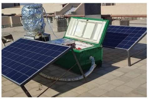
Figure 1 shows a a photograph of IESP during the experiments. IESP is fabricated from two solar photovoltaic panels (2×1 m, 550 W) connected in parallel as the power source.
A charge controller (MPPT) of 30 Amps was used to supply IESP with the optimum voltage and current. To store the electrical energy generated by the panels, two batteries (200 Ah, 12 v) were used to operate the IESP at night. An inverter (1.5 kW, 170 ~ 280 V) was used to power the pump and suction fan. A compressor (750 W) was utilized to generate a refrigerating effect in the refrigerator that also included a condenser, an expansion valve, an evaporator and a tank cooler. The pre-cooling cycle consisted of a buffer tank (100 L), a pump (19 W, 14 L min-1), a cooling cabinet (1,400×600×600 mm), a cooling coil (34 pipes with 160 fins), and a suction fan (12 m3 min-1).
Essential parts of the IESP
The IESP consists of a solar energy system (Power source), refrigerator, and pre-cooling cycle.
Solar energy system (power source)
The power source included two photovoltaic panels, a solar charge controller, a battery, an inverter, and a control system. The panels were connected in parallel. For solar arrays to produce maximum power output, they must be at an optimal tilt angle to trap maximum radiation (Tripathy et al. 2017). According to Morales and Busch (2010), the optimum tilt angle correlates with latitude and is considered equal to the latitude or latitude ±15o (+ for winter and - for summer). This system is designed to operate all year round, so the tilt angle is set to be 30° to correspond to the latitude of the test location.
Control system
This system is programmed to control the operation of the effective devices (Pump + Compressor) of IESP according to the temperature of either the buffer tank water or the cooling cabinet. The electronic system controls the operation of the hydraulic cycle of the pre-cooling mechanism. It consisted of an Arduino Uno R3, a waterproof temperature sensor, and a relay.
The buffer tank
The buffer tank is considered one of the most important parts of the cooling system. It contains the refrigerant fluid that is cooled directly by the evaporator (The evaporator of the refrigeration cycle that operates with Freon). The tank is made of a thick material to resist rust and low coefficient of thermal conductivity so as not to lose the heat stored in the fluid. It is isolated from the outside by a layer of glass wool with a thickness of 40 mm to maintain the temperatures inside the tank. The tank capacity was 100 L. The process of transferring the cooling water from the tank to the cooling coil is done by a pump. The water returns to the tank to equalize the degree of the cooling medium in the tank that (operates inside the direct cooling circuit).
The cooling cabinet
The size of the cooling cabinet was chosen to accommodate 50 kg of tomatoes to carry out the experiments. However, it is possible to re-size the room to suit commercial purposes. The dimensions of the cabinet were 1,400×600×600 mm. The side walls and bottom of the cooling cabinet were insulated by two insulating materials, namely a carbon steel layer 2 mm thick and glass wool 50 mm thick.
Experimental setup
The water flow rate was chosen at a limit that does not give temperatures less than required for pre-cooling. All experiments were carried out using a 6 L min-1 water flow rate of cooling water that passes through the cooling coil. The time for each experiment was 4 h and temperature and humidity were recorded every 20 min. The initial temperature of the cabinet was 24 °C. As for the humidity, it was monitored after placing tomatoes in the cabinet. Variables of experiments are as follows: I) The temperature of the cooling water: Experiments were carried out using three temperatures of cooling water 15, 10 and 5 °C. II) Air velocity: IESP was tested under two air velocities that passed through cooling cabinets 1.5 and 2.5 m s-1.
Measurements
Refrigeration load and Heat of respiration
The heat of respiration was calculated according to (Ashrae 2002) by the following Equation (1):
Where "Qres" is the Heat of respiration (W), "m" is the mass of tomatoes to be cooled (kg), "h" is the rate of respiration (J∙kg-1), and "n" is the operation time (hours).
Field heat
According to Sibanda (2019), field heat is the heat removed from freshly harvested tomatoes by introducing them into the cold store by reducing the field temperature of the tomatoes to the desired storage temperature. Field heat in the case of this study, therefore, is the amount of heat removed from the tomatoes as they cool from initial harvest temperature to pre-cooling temperature. The mass of the tomatoes is 50 kg, and the operating time is assumed at 4 h. The specific heat of tomatoes is 3.985 kJ•(kg °C)-1, according to Fellows (2000). The field heat calculated from the Equation (2):
Where "Qfh" is the field heat (kW), "m" is the mass of tomatoes to be cooled (kg), "Cp" is the specific heat of tomatoes (kJ•(kg °C)-1), "T2" is the pre-cooling temperature (℃) of tomatoes and "T1" is the initial tomatoes in crates temperature (℃).
Heat leakages
There is heat transfer because of leakages between the outside air and inside air through the walls and the roof as a result of the temperature gradient between the outside and inside temperature and is computed according to Ashrae (2002) by the following Equation (3):
Where "QL" is the heat leakages (W), "Uf" is the overall heat coefficient = 0.936 W•m-2 °C-1, "Af" is the surface area of the cooling cabinet (4.08 m2), "Ta" is the ambient temperature (°C) and "Tc" is the temperature of material inside the refrigerator (°C). So, the refrigeration load was estimated by the following Equation (4):
Where "1.1" is to compensate for the heat losses that may result from the frequent opening of the cooling cabinet door correspond to Thompson (2004).
Actual coefficient of performance
The solar refrigerator's efficiency is measured as the cooling capacity of solar energy absorbed by the solar collector (Mansoori and Patel 1979), following Equation (5):
Where PTotal is the total energy consumption (Refrigerator + Pump + Suction fan).
RESULTS AND DISCUSSION
Cooling cabinet temperature and humidity
At 1.5 m s-1 air velocity:
It is noticeable that the cabinet temperature decreased by decreasing the cooling water temperature from 15 to 5 °C at the same time, the cabinet humidity increased by decreasing the cooling water temperature as well. Figure 2 shows the effect of operating duration on temperature and humidity using 15 °C cooling water temperature.
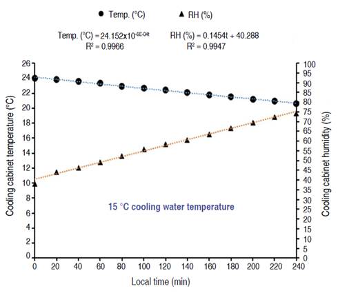
Figure 2 Effect of operating duration on temperature and humidity using 15 °C cooling water temperature.
These results indicated that the cooling cabinet temperature dropped from 24 to 20 oC while the humidity (RH) inside the cooling cabinet increased from 38.72 to 75.3% during 4 h of operation using 15 °C cooling water temperatures. Under the same experimental conditions, the temperature and humidity can be estimated from the following Equations (6) and (7):
These relationships indicate that it is possible to calculate the temperature and relative humidity (RH) inside the cabinet by knowing time (t) and the coefficient of correlation is very high and closer to 1 (R2=0.99). So, the correlation between temperature and relative humidity and between the local time is a positive strong correlation as shown in Figure (2).
Figure 3 shows the effect of operating duration on temperature and humidity using 10 °C cooling water temperature.
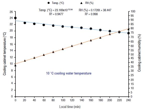
Figure 3 Effect of operating duration on temperature and humidity using 10 °C cooling water temperature.
The results showed that the cooling cabinet temperature dropped from 24 to 18.3 °C while the humidity inside the cooling cabinet increased from 37.52 to 81.2% during 4 h of operation with load using 10 °C cooling water temperatures. Under the same experimental conditions, the temperature and humidity can be estimated from the following Equations (8) and (9):
These relationships also indicate that it is possible to calculate the temperature and relative humidity (RH) inside the cabinet by knowing time (t) and the coefficient of correlation is very high and closer to 1 (R2=0.9).
Figure 4 shows the effect of operating duration on temperature and humidity using 5 °C cooling water temperature.
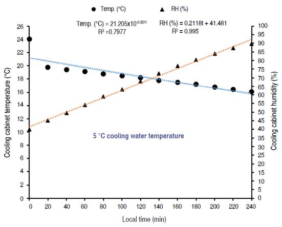
Figure 4 Effect of operating duration on temperature and humidity using 5 °C cooling water temperature.
These results indicated that the cooling cabinet temperature dropped from 24 to 16.1 °C while the humidity inside the cooling cabinet increased from 39.9 to 89.8% during 4 h of operation with load using 5 °C cooling water temperatures. Under the same experimental conditions, the temperature and humidity can be estimated from the following Equations (10) and (11):
At 2.5 m s-1 air velocity:
Figure 5 shows the effect of operating duration on temperature and humidity using 15 °C cooling water temperature.
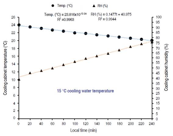
Figure 5 Effect of operating duration on temperature and humidity using 15 °C cooling water temperature.
These results indicated that the cooling cabinet temperature dropped from 24 to 20 oC while the humidity inside the cooling cabinet increased from 38.72 to 75.3% during 4 h of operation with a load using 15 °C cooling water temperatures. Under the same experimental conditions, the temperature and humidity can be estimated from the following Equations (12) and (13):
These relationships also indicate that it is possible to calculate the temperature and relative humidity (RH) inside the cabinet by knowing time (t) and the coefficient of correlation is very high and closer to 1 (R2=0.99). So, the correlation between temperature and relative humidity and between the local time is a positive strong correlation as shown in Figure (5).
Figure 6 shows the effect of operating duration on temperature and humidity using 10 °C cooling water temperature.
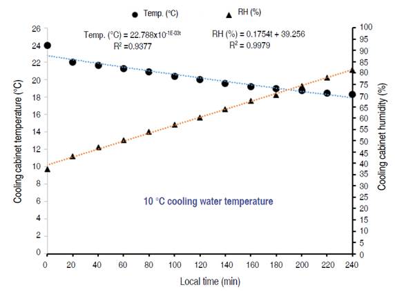
Figure 6 Effect of operating duration on temperature and humidity using 10 °C cooling water temperature.
These results indicated that the cooling cabinet temperature dropped from 24 to 18.3 oC while the humidity inside the cooling cabinet increased from 37.52 to 81.2% during 4 h of operation with load using 10 °C cooling water temperatures. Under the same experimental conditions, the temperature and humidity can be estimated from the following Equations (14) and (15):
Figure 7 shows the effect of operating duration on temperature and humidity using 5 °C cooling water temperature. These results indicated that the cooling cabinet temperature dropped from 24 to 15.4 °C while the humidity inside the cooling cabinet increased from 40 to 91.5% during 4 h of operation with load using 5 °C cooling water temperatures. Under the same experimental conditions, the temperature and humidity can be estimated from the following Equations (16) and (17):
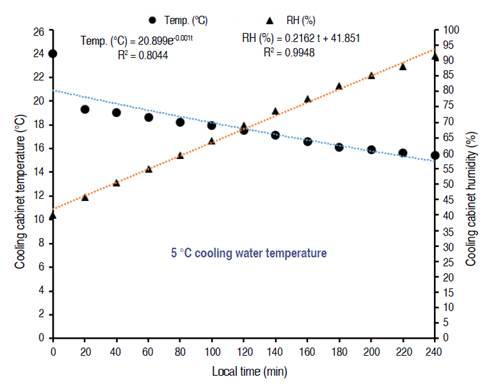
Figure 7 Effect of operating duration on temperature and humidity using 5 °C cooling water temperature.
From the results, it was found that the lowest temperature was 15.4 °C at the same time the highest relative humidity was 91.5% at 5 °C cooling water temperature.
From the previous results, it is notable that 5 °C cooling water temperature is considered optimal as it achieved the lowest temperature (16.1 and 15.4 °C) and, at the same time, it achieved the highest humidity (89.8 and 91.5%) of the cooling cabinet during 4 h of operation with load at air velocity 1.5 and 2.5 m s-1, respectively. These climatic conditions are suitable for the pre-cooling process and correspond to the recommended temperature and humidity for tomato storage (From 12 to 15 °C and RH>85%), according to Beckles (2012).
Refrigeration load
Heat of respiration
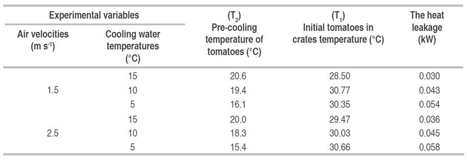
According to Suslow and Cantwell (2009), the respiration rates of tomatoes change with the change in storage temperatures, so the respiration heat was calculated according to Table 1.
Field heat
Field heat was calculated using the recorded temperatures under the variables of the experiments, as shown in Table 2.
Heat leakage
The heat leakage was calculated using the recorded temperatures under the experimental variables as shown in Table 3.
From the previous results, the refrigeration load was calculated by the following Equation (18), as shown in Table 4.
Effect of Air velocity and cooling water temperatures on refrigeration load
The results indicated that the refrigeration load increased by decreasing the water temperature from 15 to 5 °C; it also, increased by increasing air velocity from 1.5 to 2.5 m s-1. At 1.5 m s-1 air velocity, the refrigeration load was 0.176, 0.232, and 0.316 TR at cooling water temperatures of 15, 10, and 5 °C, respectively. At 2.5 m s-1 air velocity, the refrigeration load were 0.21, 0.26, and 0.338 TR at cooling water temperatures 15, 10, and 5 °C, respectively.
Actual coefficient of performance (COPcyc)
A summary of the refrigeration load and the actual coefficient of performance under the experimental variables is shown in Table 5.
Effect of air velocity and cooling water temperatures on COPcyc
The actual coefficient of performance increased by decreasing the water temperature from 15 to 5 °C and also, increased by increasing air velocity from 1.5 to 2.5 m s-1. At 1.5 m s-1 air velocity, the actual coefficient of performance were 19.4, 25.5, and 34.7% at cooling water temperatures 15, 10, and 5 °C, respectively. At 2.5 m s-1 air velocity, the actual coefficient of performance was 23.1, 28.8 and 37.2% at cooling water temperatures 15, 10, and 5 °C, respectively. The use of 5 °C cooling water temperature has achieved the highest COPcyc at 1.5 and 2.5 m s-1 air velocities.
CONCLUSION
To achieve sustainable development of the agricultural sector, renewable energy should be relied upon to operate electrical energy-consuming systems, especially in developing countries. In this study, an IESP was successfully fabricated and tested to promote food security. It is completely powered by solar energy and is compact in size and transportable. The IESP performance proved a very feasible solution to the demands of small and medium horticultural holdings. From the experimental results, it can be observed that 5 °C cooling water temperature is considered optimal as it achieved the lowest temperature and at the same time it achieved the highest humidity. Based on the findings of this study, these climatic conditions are suitable for the pre-cooling process and correspond to the recommended temperature and humidity for tomato storage. So, the pre-cooling process is considered one of the most important techniques for handling horticultural crops to reduce post-harvest losses. However, choosing the appropriate pre-cooling technology is crucial to ensuring economical operation and sustainability.


