1. Introduction
The study of fluvial deposits is essential in improving our understanding of hydrocarbon reservoirs, leading to more effective hydrocarbon production (Miall, 2006; Owen et al., 2017). That is because the internal architecture and petrophysical properties of fluvial reservoirs are generally complex and heterogeneous (e.g., Owen et al., 2015; Larue et al., 2023). Recently, considerable research has been conducted on the properties and quality of subsurface fluvial reservoirs using geophysical methods (e.g., Abdel-Fattah et al., 2022; El-Gendy et al., 2022; Tayyab Naseer et al., 2022). However, there is always a need for analog data from outcrops to enhance the subsurface geological reservoir models of fluvial deposits (e.g., Owen et al., 2017).
The sedimentary rift basins of Sudan were discovered through geophysical surveys conducted by Chevron company in cooperation with the Sudanese government (Schull, 1988). The discovered basins, such as Muglad Basin, represent major components of the West and Central African Rift System (WCARS) and proved to be of high economic importance in terms of hydrocarbon production (Fig. 1; Schull, 1988; Fairhead, 1988a; Mohamed et al., 2001). The Shendi Formation is the focus of this study, and it represents most of the exposed part of the succession of the Shendi-Atbara Basin in Sudan (Fig. 1).
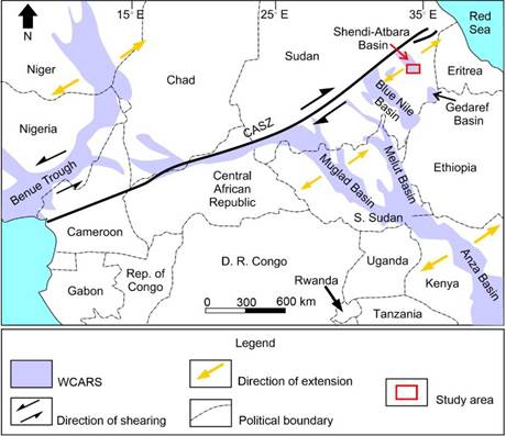
Figure 1 Tectonic model of the West and Central African Rift System (WCARS) and the Central African Shear Zone (CASZ). The red arrow and rectangle represent the Shendi-Atbara Basin and study area (Modified after Fairhead, 1988b).
Economic hydrocarbon reserves have not been discovered in Shendi-Atbara Basin. In 2011, Kandaka-1 well was drilled in the basin, about 60 km east of Ed Damer city (Fig. 2A), for exploration purposes but without encouraging discoveries (Sudan Ministry of Oil and Gas, 2011). On the other hand, the Muglad Basin that extends from southwestern Sudan into South Sudan (Fig. 1) is the largest rift basin in the country and the primary source of hydrocarbon production (Makeen et al., 2021a). The main reservoir in this basin is the Cretaceous Bentiu Formation which is similar in depositional style to the Shendi Formation (Mohamed and Mohammed, 2008; Makeen et al., 2021b). Bentiu Formation consists of thick sandstone sequences deposited in braided and meandering systems (Schull, 1988; Mohamed et al., 2001; Mohamed and Mohammed, 2008; Makeen et al., 2021b). In addition, Melut Basin (Fig. 1) is one of the major oil-producing rift basins in South Sudan with its primary reservoirs being the Upper Cretaceous and Paleogene Sandstones (Dou et al., 2007). The Upper Cretaceous Sandstones were deposited in sandy fluvial and shallow lacustrine environments, while the Paleogene deposits were deposited in a braided deltaic environment (Dou et al., 2007). Arising from the similarity in the depositional environments, this study provides additional information about the architectural elements and heterogeneity in the fine-scale which is hardly studied by large-scale seismic sections. Therefore, integrating different subsurface data with outcrop analogs can fill the gap in scale and resolution.
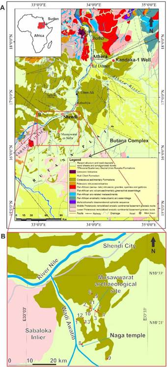
Figure 2 A) The geological map of the study area and the vicinity (modified after Whiteman, 1971; GRAS, 2004). The inset at the upper left corner represents the location of the geological map relevant to Sudan and Africa. The red outlined rectangle represents the study area shown in B. B) A closer view of the study area showing the locations of the thirteen (13) studied outcrops.
Several studies were conducted on the sedimentology and stratigraphy of the Shendi-Atbara Basin (e.g., Kheiralla, 1966; Whiteman, 1971; Awad and Schrank, 1990; Wycisk, 1991; Werner, 1993; Germann et al., 1994; Bussert, 1998; Eisawi et al, 2015; Salih et al., 2015; Harzhauser et al., 2017; Bussert et al., 2018). Although Bussert (1998) studied some outcrops in the Naga area (Wadi Awatib area), detailed sedimentological and facies architecture of outcrops in Musawwarat area, to the northeast of Naga area, have not been reported. Moreover, the majority of the previous studies on Shendi-Atbara Basin were principally based on measured vertical profiles (e.g., Bussert, 1988) that could barely be sufficient to describe the depositional environments (Miall, 1985). The main reason is that misinterpretations of geometry and complex internal forms may occur when deductions are based only on vertical facies variations (Miall, 1985, 2006). Therefore, this study considers lateral and vertical changes in lithofacies and architecture to conduct a better interpretation of the depositional environment of the sedimentary rocks of the Shendi Formation in Musawwarat-Naga area. The study also aims at deducing the provenance and tectonic setting of the sediments by integrating petrographic and paleocurrent analysis. These findings will provide an outcrop analog for similar subsurface deposits in the basin and the region in terms of architecture and depositional environment.
The studied outcrops are located in Musawwarat-Naga area in River Nile State, north-central Sudan (Fig. 2). This area was chosen for this study due to the availability of sufficient outcrops that are mainly the results of the ancient quarries and excavation activities. The exposures are generally in the form of plateaus cut by numerous wadis. The thickness of the outcropping sections reaches up to 45 m. Although the outcrops are massive and of great heights in this area, only a few exposures occur due to the desert varnish effect.
2. Geological Setting
The Shendi-Atbara Basin is located in central Sudan and represents an outlier where younger sedimentary rocks (mainly of Cretaceous age) are surrounded by the older basement. The basin is a northwest-southeast-trending rift basin and is part of the West and Central African Rift System (WCARS) which extends from west Africa to Sudan (Fig. 1; Schull, 1988; Fairhead, 1988; Klitzsch and Squyres, 1990; Ibrahim et al., 1996). The formation of intra-continental basins in Africa was a result of the breakup of Gondwana in the Mesozoic Era, where the African continent separated from South America (Binks and Fairhead, 1992). Extensional pull along the Central African Shear Zone (CASZ) resulted in crustal thinning, mantle upwelling, and consequent rifting and subsidence. These processes resulted in the formation of the rift basins in Sudan including the Shendi-Atbara Basin (Schull, 1988; Fairhead, 1988; Ibrahim et al., 1996; Salama, 1997).
The Shendi-Atbara Basin represents a half-graben structure, with sediments thickness of over 3000 m, based on geophysical gravity modeling (Jorgensen and Bosworth, 1989). The main sedimentary units of the basin include Cretaceous Strata, which lie unconformably on the Basement Complex, and Recent Alluvium and Wadi Deposits (Fig. 2; Whiteman, 1971). The stratigraphy of Shendi-Atbara Basin is composed of Bagrawiya Formation (Turonian-Coniacian), Mahmiya Formation (Coniacian-Campanian), Shendi Formation (Campanian-Maastrichtian), Hudi chert Formation (Eocene-Oligocene), and Wadi Awatib Conglomerate (late Miocene-early Pliocene) (Fig. 3; Eisawi et al., 2015; Bussert et al., 2018).
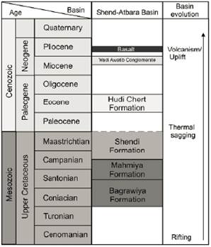
Figure 3 Stratigraphic chart of Shendi-Atbara Basin showing the rock units succession and the basin evolution (Modified after Eisawi et al., 2015; Bussert et al., 2018).
The Shendi, Hudi Chert, and Wadi Awatib formations are exposed on the surface, whereas Bagrawiya and Mahmiya Formations are encountered only in the subsurface (Fig. 3; Bussert et al., 2018). The Shendi Formation was previously correlated with the Albian-Cenomanian Omdurman Formation to the south and Wadi Milk Formation to the west (Awad and Schrank, 1990; Wycisk, 1991; Werner, 1993; Agyemang et al., 2019). However, Eisawi (2015) suggested a Campanian-Maastrichtian age for the formation based on palynological evidence.
Kheiralla (1966) described the Shendi Formation as being composed of pebble conglomerates, intraformational conglomerates, sandstones, and mudstones. The sandstones were described as well-bedded, non-pebbly, clean, and very well-sorted, consisting mainly of quartz grains cemented with iron oxides (Kheiralla, 1966). Bussert (1998) reported that the Shendi Formation was deposited in a fluviatile system, mainly of braided and meandering nature. It is believed that such fluviatile systems changed gradually, with time, from braided into meandering river systems by the Late Cretaceous (Bussert, 1998). Moreover, lacustrine sedimentation as a result of post-rift activities was also reported in some parts of the basin (Klitzsch and Squyres, 1990; Oshi, 2004).
3. Materials and Methods
3.1 Fieldwork methods
Fieldwork was carried out on the outcropping sections of Shendi Formation. Outcrops were selected for this study based on accessibility and adequate vertical and lateral extension of the exposure. Field observations on thirteen outcrops (Fig. 2) included examining different lithofacies types and the main classification criteria were lithology, grain size, internal structure, and geometry. A Garmin Oregon 450t GPS device was used to take coordinates and elevations of the studied sections while a geologic clino-compass was used to measure the palaeocurrent directions. Samples were collected from different locations and beds representing the dominant lithofacies types. Efforts were made to obtain fresh samples at each location. The samples were then kept in labeled sample bags for subsequent analyses. Field photographs of features of interest were taken using a Nikon D3100 DSLR camera. Representative vertical and lateral sedimentary profiles with a total thickness of 222 m were measured from 13 outcrops based on the quality of the exposures (Table 1; Fig. 2). Different lithofacies have been identified, described, and named based on the facies scheme of Miall (1978). Architectural elements were identified based on the concepts of Allen (1983) and Miall (1985). Bounding surfaces were traced on photographs and then interpreted according to Miall (1985).
Table 1 Location coordinates and profiles thicknesses of the measured outcrops
| Profile No. | Latitude | Longitude | Profile Thickness (m) |
|---|---|---|---|
| 1 | 16° 22' 22.9" | 33° 15' 33.2" | 62 |
| 2 | 16° 24' 51.8" | 33° 18' 47.1" | 8 |
| 3 | 16° 24' 23.8" | 33° 20' 6.1" | 26 |
| 4 | 16° 24' 18.1" | 33° 20' 20.3" | 6 |
| 5 | 16° 27' 32.7" | 33° 19' 40.4" | 5 |
| 6 | 16° 28' 9.9" | 33° 19' 17.2" | 21 |
| 7 | 16° 24' 28.1" | 33° 20' 69.2" | 12 |
| 8 | 16° 16' 23.8" | 33° 16' 47.3" | 4 |
| 9 | 16° 12' 49.7" | 33° 22' 54.8" | 17 |
| 10 | 16° 24' 38.7" | 33° 19' 8.4" | 11 |
| 11 | 16° 24' 41.4" | 33° 19' 5.3" | 12 |
| 12 | 33° 17' 19.8" | 33° 17' 24" | 8 |
| 13 | 16° 21' 29.3" | 33° 17' 19.8" | 30 |
| Total Thickness | 222 |
3.2 Thin section petrography
Fifteen (15) representative sandstone samples were selected for petrographic analysis. The sandstones were impregnated with epoxy resin before cutting. Each sample was mounted on a glass slide using Canada balsam and examined under a petrological microscope model Lomo Polam R-211M. The framework composition (quartz, feldspar, and lithic fragments) and porosity of each sample were approximately estimated using the conventional point counting method (100 points). Ternary plot diagrams of framework composition percentages (Dickinson and Suczek, 1979) for the tectonic setting were plotted. Photomicrographs of features of interest were taken using a Nikon Coolpix camera and the classification of the sandstones was based on Folk (1974).
4. Results and Discussion
4.1 Lithofacies Description andInterpretation
The deposits in the studied successions mainly comprise sandstones and conglomerates, while mudstones are minor. Eight sedimentary lithofacies were identified, namely, stratified conglomerate (Gt), matrix-supported massive conglomerate (Gmm), trough cross-bedded sandstone (St), massive sandstone (Sm), horizontally bedded sandstone (Sh), laminated sandstone (Sl), massive mudstone (Fm) and iron crusts (Fc). The approximate relative abundance of each lithofacies in the total succession is shown in Figure 4. Table 2 summarizes the information for each lithofacies. Selected vertical sedimentary profiles of the studied successions are shown in Figure 5. Lithofacies description and coding followed the scheme of Miall (1978, 2006). The description and interpretation of each lithofacies are given in the following section.
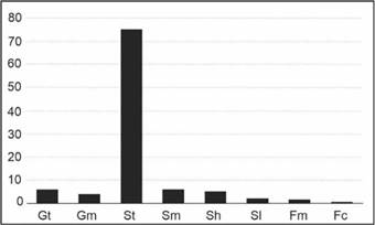
Figure 4 Relative abundance (in percentages) of lithofacies types in the total succession of the studied locations. Gt= stratified conglomerate, Gmm= matrix-supported massive conglomerate, St= trough cross-bedded sandstone, Sm= massive sandstone, Sh= horizontally bedded sandstone, Sl= laminated sandstone, Fm= massive mudstone, and Fc= iron crusts.
Table 2 Summary of the description and interpretation of lithofacies encountered in the study area (modified after Miall, 2006).
| Lithofacies Code | Lithofacies Name | Structure | Textural Characteristics | Interpretation |
|---|---|---|---|---|
| Gt | Stratified conglomerate | Cross stratification | Pebbles (1 cm-5 cm), moderately-poorly sorted | Deposition by Traction currents and high-energy flows (Ghazi and Mountney, 2009; Bussert et al., 2018) |
| Gmm | Matrix-supported massive conglomerate | Massive | Pebbles (4 mm-5 cm), Poorly sorted | plastic debris flows (Miall, 1978) |
| St | Trough cross-bedded sandstone | Trough cross-bedding | Medium to pebbly coarse-grained sand, moderately to poorly sorted | High energy and low sinuosity streams (Rust, 1977; Hjellbakk, 1997; Miall, 2006) |
| Sm | Massive sandstone | Massive | Fine to pebbly coarse-grained sand, moderately to poorly sorted | Rapid deposition by sediment-gravity flow (Miall, 2006) |
| Sh | Horizontally bedded sandstone | Horizontal bedding | Fine to medium-grained sand, moderately sorted | Upper flow regime or high energy currents (Hjellbakk, 1997; Miall, 2006) |
| Sl | Laminated sandstone | Parallel lamination | Very fine to fine-grained sand, moderately sorted | Deposition in the terminal waning stage of seasonal flood events (Miall, 2006) |
| Fm | Massive mudstone | Massive | Silt and clay | Deposition from suspension during periods of quiet waters (Miall, 2006) |
| Fc | Iron crusts | Massive, nodular, and colloform structures | No grains | Chemical precipitation and diagenesis (Carozzi, 1960; Boggs, 2006) |
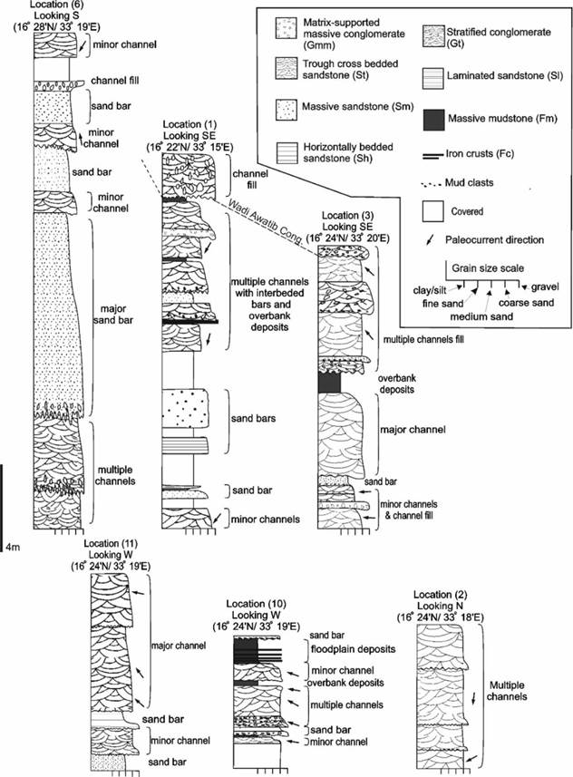
Figure 5 Interpretation of selected vertical sedimentary profiles of the studied outcrops in locations 1, 2, 3, 6, 10, and 11.
4.1.1 Stratified conglomerate (Gt)
This lithofacies exhibits slightly inclined cross stratification, and it consists of pebbles of predominantly extraformational origin accompanied by minor intraformational mudstone clasts. The mudstone clasts are concentrated along the erosional lower boundary of this facies. These mud clasts are angular to sub-angular, poorly sorted, and gradually fine and disappear upwards (Figs. 6B). The extraformational clasts consist mainly of light brown chert pebbles and cobbles which range in size from 1 cm to 5 cm. The chert clasts are generally moderately sorted and rounded to sub-rounded. The clasts are iron-cemented and the matrix is composed of medium- to coarse-grained quartz sand (Figs. 6F). The conglomerate clasts exhibit crude to random orientation forming tabular-shaped stacking which may represent bedding planes but cannot be used to deduce the paleocurrent direction. These conglomerates represent the uppermost facies in the outcrops they are found in.
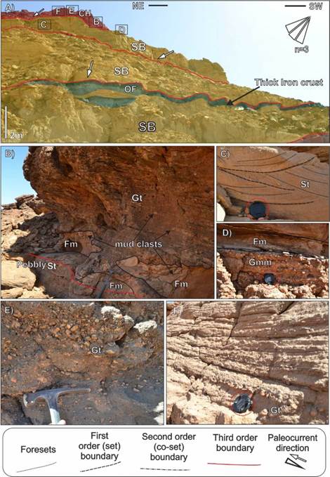
Figure 6 A) Lateral profile of location 1 outcrop showing sandy bedforms element (SB) (yellow-shaded) overlain by overbank fines elements (OF) (green-shaded) and channel fill elements (CH) (red-shaded). B) Stratified conglomerate (Gt) containing mud clasts at the base and overlaying trough cross-bedded sandstone facies (St) with an erosional contact. C) Small-scale trough cross-bedded sandstone (St) showing foresets and first-order bounding surfaces. D) matrix-supported conglomerate (Gmm) overlain by thin massive mudstone (Fm) and a thin iron crust. E) and F) Stratified conglomerate facies (Gt) on top of the outcrop. Hammer's length is 30 cm, and the camera lens cover diameter is 5 cm.
Interpretation: The slightly inclined cross stratification indicates that the conglomerates were mainly transported by traction currents and deposited in high-energy flows (Ghazi and Mountney, 2009; Bussert et al., 2018). The lower erosional boundary in these facies also supports deposition by high-energy flows (Miall, 2006). The clasts of this facies exhibit crude orientation and tabular-shaped stacking which indicate deposition under a high-velocity flow in fluvial channels (Kim et al., 2009, Ghazi and Mountney, 2009). Moreover, the crude lamination and the high matrix percentage indicate deposition under sediment gravity flow as channel fill (Miall, 2006). This lithofacies is not part of the Shendi Formation and it represents part of the newly assigned late Miocene-early Pliocene Wadi Awatib Conglomerate but it was included because it represents the upper limit of Shendi Formation (Bussert et al., 2018).
4.1.2 Matrix-supported massive conglomerate (Gmm)
This facies is massive and is mainly composed of extraformational, poorly sorted, and well-rounded to rounded quartz pebbles of various colors. The clasts range in size from 4 mm to 5 cm, and they are supported by a matrix of quartz sandstone composition and are cemented by iron oxides (Figs. 6D and 7B). This facies is often underlain and overlain by trough cross-bedded sandstone facies (St) (Fig. 7A and 7B). The lower boundary is dominantly erosional, slightly concave, and contains intraformational mudstone clasts. The upper contacts are sharp and sometimes gradational.
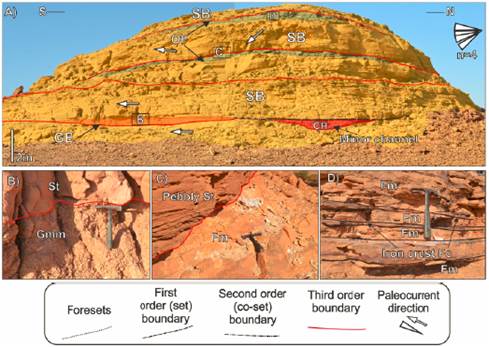
Figure 7 A) Lateral profile of location 10 outcrop showing sandy bedforms elements (SB) (yellow-shaded), gravelly bars and bedforms element (GB) (orange-shaded), channel fill elements (CH) (red-shaded) and overbank fines elements (OF) (green-shaded). B) Matrix-supported massive conglomerate facies (Gmm) overlain by trough cross-bedded sandstone facies (St). C) Massive mudstone facies (Fm) overlain by trough cross-bedded sandstone facies (St). D) interbedded massive mudstone facies (Fm) and iron crusts facies (Fc). The hammer length is 30 cm.
Interpretation: This facies is deposited by plastic debris flow, and it is attributed to longitudinal bars and lag deposits (Miall, 1978). The slightly concave up lower boundary of the Gmm facies is a result of erosion at the beginning of the deposition (Miall, 2006).
4.1.3 Trough cross-bedded sandstone facies (St)
The trough cross-bedded sandstone facies (St) is the predominant facies in the study area, representing more than 70% of the total succession. Moreover, this facies is present in all of the studied locations (Figs. 6-11). This lithofacies has varying colors such as red, yellow, and white, but the surface weathering color is light brown. The sand grains are commonly medium to coarse-grained and sometimes pebbly, especially in the base of the bed. The grains are moderately to poorly sorted and sub-angular to sub-rounded. Several sets and cosets of trough cross-bedding are present in this facies. The thickness of the individual set varies significantly from one bed to another, and it ranges from small-scale sets of an approximate thickness of 20 cm to 1m in large-scale sets. The cross-bedding allows the measurement of paleocurrent directions and this was the only structure used for such measurements. It is often underlain by conglomerates or the lower cycle mudstones. The lower boundary of this facies is usually erosional.
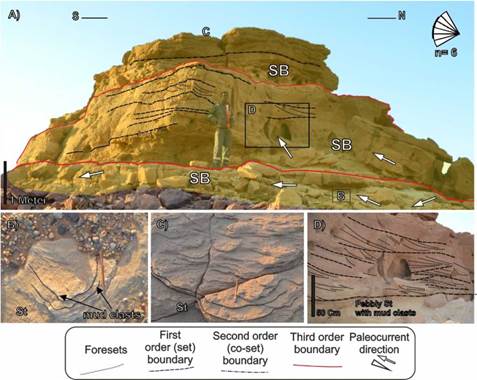
Figure 8 A) Lateral profile of location 4 showing sandy bedforms elements (SB) (yellow-shaded). B, C) A plan view of the trough cross-bedded sandstone facies (St). D) Trough cross-bedded sandstone facies (St) in cross-section view. At the base the sandstone is pebbly and contains mudclasts.
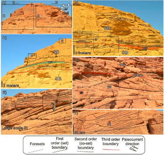
Figure 9 A) General view of location 11 outcrop. B), C) Lateral profiles of location (11) showing sandy bedforms element (SB) (yellow-shaded), gravelly bars and bedforms element (GB) (orange-shaded) and overbank fines element (OF) (green-Shaded). D) Trough cross-bedded sandstone facies (St) overlain by horizontally bedded sandstone facies (Sh) with interbedded thin matrix-supported massive conglomerate (gmm). E), F) Large-scale trough cross beds. Hammer's length is 30 cm, and the camera lens cover diameter is 5 cm.
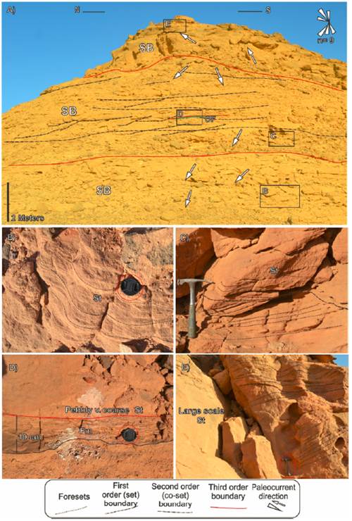
Figure 10 A) Lateral profile of location 3 outcrop Showing sandy bedforms elements (yellow-shaded) and a thin overbank fines element (OF) (green-shaded) which is shown in a close up view in D. B) Plan view of small-scale trough cross-bedded sandstone (St). C) Small-scale trough cross-bedded sandstone facies (St). D) Massive mudstone facies (Fm) interbedded with very coarse trough cross-bedded sandstone facies (St). E) Large-scale trough cross-bedded sandstone (St). The hammer length is 30 cm, camera lens cover diameter is 5 cm.
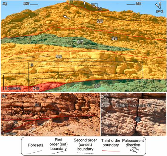
Figure 11 Lateral profile of location 7 outcrop showing sandy bedforms elements (yellow-shaded), channel fill element (CH) (red-shaded) and overbank fines elements (OF) (green-shaded). B) Massive mudstone facies (Fm) overlain by trough cross-bedded sandstone (St). C) Pebbly trough cross-bedded sandstone (St). The camera lens cover is 5 cm.
Interpretation: This facies is interpreted to be deposited as three-dimensional (3D) dunes that are attributed to high energy rivers or higher velocity currents which are some of the characteristics of braided, low sinuosity streams (Rust, 1977; Hjellbakk, 1997; Miall, 2006). In contrast, lower energy, high sinuosity streams are characterized by two-dimensional dunes which result in the formation of planar cross-beds (Rust, 1977; Miall, 2006).
4.1.4 Massive sandstone (Sm)
This facies is massive and is composed of fine-to coarse-grained, moderately-to poorly-sorted sand with some pebbles (Fig. 6A).. The color is reddish, yellowish to white. It is often found underlain by trough cross-bedded sandstone facies (St). The lower boundary is often a non-sharp, gradual contact, while the upper contact usually ends with massive mudstone facies (Fm).
Interpretation: The massive sandstone is suggested to be deposited by rapid sedimentation during falling flow conditions (Miall, 2006; Aloui et al., 2012). The rapid dumping of sediments does not allow the hydraulic factor to produce any sedimentary structures (Hjellbakk, 1997).
4.1.5 Horizontally bedded sandstone (Sh)
The horizontally bedded sandstone (Sh) consists of fine-to-medium-grained, moderately-sorted sandstones that are characterized by horizontal bedding. This facies is commonly found overlain and underlain by trough cross-bedded sandstone facies (St) (Fig. 9D). The thinkness of the beds ranges between 5 to 20 cm. The lower and upper boundaries are usually sharp but sometimes the lower boundary is gradual.
Interpretation: The horizontally bedded sandstone is interpreted to be deposited as plane beds under conditions of upper flow regime (Miall, 2006). This facies can as well be interpreted as bar-top of large flat sand bars that are deposited by high energy currents (Hjellbakk, 1997).
4.1.6 Laminated sandstone (SL)
The laminated Sandstone (Sl) represents only 2% of the total succession of the studied sections. This facies consists of very fine to fine, thin horizontally parallel laminated sandstone intercalated in some cases with iron crusts (Fc) (Fig. 6A). This facies is commonly overlain by massive mudstone facies (Fm) and is often underlain by trough cross-bedded sandstone facies (St) with a gradual contact.
Interpretation: The small-scale sedimentary structures and fine-grained lithology indicate deposition as bar-top sand sheets during the terminal waning stage of seasonal flood events (Miall, 2006).
4.1.7 Massive mudstone (Fm)
This facies represents a minor percentage, less than 2% of the total succession (Fig. 7). This facies consists of silt and clay sizes. The color of the mudstones varies from grey to white. This facies is commonly found inter-bedded with thin crusts of iron (Fc) (Fig. 7D). It is often found overlain and underlain by trough cross-bedded sandstone facies (St) and the upper contact is usually erosional (Figs 7C, 10D, and 11B). The mudstones commonly form thin beds (less than 50 cm).
Interpretation: This facies is deposited from suspension during periods of quiet waters, for example in overbank or abandoned channel deposits. However, the larger thicknesses of this facies can be interpreted as floodplain or swamp deposits (Miall, 2006). The scarcity of fossils or root fossils in these mudstones indicates that the environment is not suitable for them due to climatic conditions (Ghazi and Mountney, 2009).
4.1.8 Iron crusts (Fc)
The iron crusts (Fc) show nodular and colloform structures and is generally found in association with and, often, on top of the massive mudstone facies (Fm) (Figs. 6A and 7D). This facies ranges in color from black to red. There are no obvious grains in this facies. Generally, the thickness of this facies ranges from abundant thin crusts (up to 10 cm thick) and less frequent thicker beds which can reach more than 50 cm.
Interpretation: This facies is the only non-clastic facies encountered in the studied sections. The Iron crusts are the results of the chemical precipitation of iron oxides that are dissolved in the water. The iron crusts are mainly deposited during periods of floods and water stabilization periods (Boggs, 2006). However, a secondary origin of the iron oxides might be possible through early diagenesis caused by circulating solutions and oxidation of iron-bearing minerals (Carozzi, 1960).
4.2 Sedimentary architectural elements
Based on the classification of Miall (1985, 2006), four architectural elements were recognized, namely; channel fill (CH), sandy bedforms (SB), gravelly bars and bedforms (GB), and overbank fines (OF). The information on each element is summarized in Table 2. The properties which characterize the different elements are facies association, geometries, and bounding surfaces (Allen, 1983; Miall, 1985). The sandy bedforms elements (SB) were found to be the predominant elements in the study area. Selected lateral profiles showing the architectural elements identified in the studied outcrops are shown Figures 6-11.
4.2.1. The hierarchy of bounding surfaces
The hierarchy ranges from the first-order bounding surfaces of individual cross-bed sets to the large-scale fourth-scale bounding surface of paleovalleys and channel belts (Allen, 1983; Miall, 1985). The first-order bounding surface represents the contact between individual cross-bed sets such as the trough cross-bedded sandstone facies (St) sets (Fig. 6C; Allen, 1983; Miall, 1985). The second-order surfaces bound co-sets or individual sedimentary bodies that are genetically related such as the co-sets formed by the stacking of individual groups of cross-bed sets in the trough cross-bedded sandstone facies (St) (e.g., Fig. 8D and Fig. 10A). The third-order surfaces are erosional surfaces that bound groups of sedimentary bodies (e.g., Fig. 6A). Fourth-order surfaces that define the boundaries of paleovalleys and channel belts have not been identified in the studied outcrops as they need a wider lateral exposure which is not available in the study area. A brief description and interpretation of the architectural elements found in the study area are given in the following section.
4.2.2 The sandy bedforms elements (SB)
The sandy bedforms elements (SB) are composed of stacked sets, arranged into fining-upward packages of sandstone. These elements are the most dominant and they are found in all of the studied outcrops (Figs. 6-11). A cyclic arrangement is occasionally encountered showing a fining upward style that typically starts with a basal matrix-supported pebbly trough cross-bedded sandstone (St) facies that has an erosional lower contact with the underlying cycle (e.g., Fig. 7A). Such cycles might also contain horizontally bedded sandstones (Sh), massive sandstone (Sm) and laminated sandstone (Sl) and mostly end with massive mudstone (Fm) and iron crusts (Fc). These fining upward cycles can be seen in some of the measured vertical profiles shown in Fig. 5 and in the lateral profiles such as in Fig. 6A and Fig. 7A. The SB elements extend laterally up to hundreds of meters and usually occur in sheets geometry and the thickness ranges from 1 m up to 10 m.
Interpretation: The prevalence of trough cross-bedded sandstone facies (St) and large-scale ones in particular among the sandy bedforms elements (SB) indicate the deposition of the sandy bedforms elements (SB) in the active channels as a product of the migration of dune-scale bedforms (Miall, 1985).
4.2.3 The channel fill elements (CH)
The channel fill elements (CH) in the studied outcrops are generally characterized by erosive-based units that cut down into fine-grained floodplain sediments of the underlying cycle. The observed channels are often limited in lateral extension with the channel base often forming irregular and concave-up erosional surfaces. The fill of the channel elements is characterized by a fining upward sequence that typically starts at the base with matrix-supported massive conglomerate (Gmm) and gradually fines into trough cross-bedded sandstone (St) (e.g., Fig. 7A). The base of each channel represents a third order erosional boundary. The lower boundary is often slightly concave-up and might show some mud clasts while the upper boundary is often a sharp, non-erosional contact. Location 10 (Fig. 7A) shows a minor channel that has a width of about 3 m and a depth of 1 m. The limited lateral extension of the outcrops does not allow the recognition of major channels that represent the paleovalley that extend for kilometers. In contrast, the minor channels that infill the major channels can have a lateral extension of few meters.
Interpretation: The presence of these elements in a fining upward order can prove the existence of the channel (Miall, 2006). The Channel fill elements (CH) are also interpreted as fluvial channels (Miall, 1985). The lower erosional surface of these elements indicate deposition by high-energy flows (Miall, 2006). Allen (1983) attributed the stacking of minor channels to deposition in low sinuosity streams. This aggradation of channels and their shallow depth (e.g., Fig. 7A) suggest deposition in a braided fluvial system where the relatively rapid and continuous migration of channels does not allow for deeper incisions (Miall, 1985; Bristow, 1987)
4.2.4 Gravelly bars and bedforms elements (GB)
Gravelly bars and bedforms elements (GB) in the study area consist of matrix-supported massive conglomerate facies (Gmm) (Fig. 7A and Fig. 9B). GB elements are always found interbedded with channel fill elements (CH) and sandy bedforms elements (SB). The lower boundary of these elements is usually erosional and often corresponds to the third-order bounding surfaces of the sandy bedform elements (SB) as in Fig. 7A and Fig. 9B. Geometrically, these elements usually have elongated, wedged shapes with limited lateral extensions of about 10 m. The thickness approximately ranges between 0.5 m to 1 m.
Interpretation: The gravelly bars and bedforms elements (GB) are interpreted as longitudinal bars or lag deposits that migrate downstream during floods and high water (Miall, 1985, 2006; Ghazi & Mountney, 2009). The longitudinal bars interpretation is supported by the wedged shape and the limited lateral extension of these elements (Miall, 1985).
4.2.5 Overbank fines elements (OF)
Overbank fines elements (OF) represent thin blankets of mudstone (Fm) with very fine-grained sandstone beds intercalated with thin Iron crusts (Fc) (e.g., Fig. 7A and Fig. 11A). these elements occur in thin wedge-shaped lenses and blankets. These elements typically occur at the top of the sandy bedform elements (SB) as seen in Fig. 7A. They commonly occur in wedge shapes (e.g., Fig. 11A) and sheets (e.g., Fig. 7A). The thickness is generally thin (less than 50 cm) and the lateral extension ranges from 5 m to 15 m.
Interpretation: The fine grained nature of the overbank fines elements (OF) suggests the deposition as floodplain deposits in distal areas to the main channel during waning flood events (Miall, 1977a, 2006; Ghazi and Mountney, 2009).
4.3 Sandstone petrography
The results of sandstone petrography and the classification of each sandstone sample are shown in Table 4. Quartz-feldspar-lithic fragments (QFL) framework composition ternary plot for the classification of sandstones based on the concept of Dott (1964) and Pettijohn et al. (1987) is shown in Figure 12A. A ternary plot for the tectonic setting of the sandstones based on the concept of Dickinson and Suczek (1979) is shown in Figure 12B. The classification of the sandstone samples revealed that the majority are quartz arenite, while two samples are sublitharenite. In all samples, quartz grains represent about 90% or more of the compositional framework, while feldspars and lithic fragments occur in low percentages (0-10%). Quartz grains generally appear colorless in plane-polarized light and contain minor inclusions and cracks (Figs. 13A and 13C). The quartz grains are predominantly mono-crystalline (Fig. 13B, Fig. 13D, Fig. 14B, and Fig. 14D) representing approximately 90% while the poly-crystalline grains (Figs. 13B and Fig. 14B) are minor (10%). Generally, the poly-crystalline grains are larger than the mono-crystalline grains and contain sutured crystal contacts (Fig. 13B and Fig. 14B). Stretched quartz grains also occur in lesser abundance (Fig. 13D).
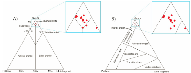
Figure 12 A) Ternary plot diagram for the classification of sandstones based on the quartz-feldspar-lithic fragments (QFL) framework composition percentages (After Dott, 1964; modified by Pettijohn et al., 1987). The inset shows a close up view of the region where samples fall. The majority of the samples fall in the quartz arenite region, while two samples fall in the sublitharenite region. B) Ternary plot diagram of QFL framework composition percentages for tectonic setting (modified after Dickinson and Suczek, 1979. The inset shows a close up view of the region where samples fall. The majority of the samples fall in the interior craton region, while only one samples fall in the recycled orogen region.
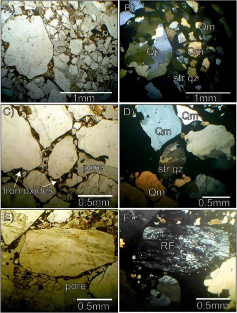
Figure 13 Photomicrographs of the studied sandstone. A) and B) sample (L5P1S1) from location 5 (St facies, quartz arenite, v. coarse to coarse, poorly sorted, sub-rounded to sub-angular grains, cemented by iron oxides, matrix < 5%) shows Qp, Qm, and stretched quartz. C) and D) sample (L3P1S2) from location 3 (St facies, quartz wacke, v. coarse, poorly to v. poorly sorted, sub-rounded to sub-angular grains, cemented with iron oxides, the matrix is 10%, shows pore space and stretched quartz. E) and F) sample (L3P1S2) from location 3 shows a large lithic fragment. Str Qz= stretched quartz, Qm= monocrystalline quartz, Qp= polycrystalline quartz, RF= rock fragment. Plane-polarized light photomicrographs are shown to the left, and cross-polarized light to the right.
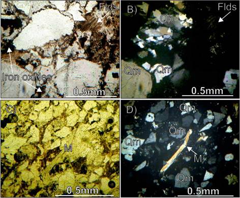
Figure 14 Photomicrographs of the studied sandstone. A) and B) sample (L6P1S3) from location 6 (Sm facies, quartz arenite, coarse, moderately sorted, sub-angular to angular grains, cemented by iron oxides, matrix < 5%) shows altered feldspar. C) and D) samples (L10P1S8) from location 10 (Sm facies, quartz arenite, fine, moderately to well-sorted, sub-angular to angular grains, cemented with iron oxides, the matrix is 5%) shows elongated muscovite grain. Flds= feldspar, M= mica (muscovite), Qm= monocrystalline quartz, Qp= polycrystalline quartz. Plane-polarized light photomicrographs are shown to the left and cross-polarized light to the right.
Lithic fragments generally represent less than 10% of the total framework composition (Figs. 13E and Fig. 13F). Generally, the sandstone samples contain a relatively high amount of muscovite mica (Figs. 14C and Fig. 14D) (approximately 5%). The source of muscovite is suggested to be granitic or schistose rock (Adams et al., 1988). The feldspars approximately represent less than 4% of the compositional framework. Feldspar grains found in the sandstones are altered, and some grains show polysynthetic twinning which characterizes plagioclase feldspars (Figs. 14A and Fig. 14B).
Generally, the sandstones are moderately to poorly sorted, and the roundness of the grains is mainly sub-angular to sub-rounded. The main cementing material is iron oxides, and the matrix is generally less than 10%. According to Folk (1974), these sandstone samples are mostly texturally sub-mature. The textural maturity is not in concordance with the high mineralogical maturity. This discordance can be attributed to a high degree of chemical weathering at the time of transportation and deposition of the sediments (Late Cretaceous), which resulted in the leaching of less stable minerals (Chandler, 1988; Johnsson et al., 1988). This is evidenced by the tropical, warm, and humid climate that prevailed in the area during that period (Germann et al., 1994). However, the lower percentages of less stable minerals such as feldspar and mica in the sandstone may also be attributed to the mineral composition of the sources rocks (Boggs, 2006). The sandstones are mostly cemented by iron oxides that are believed to be of a secondary origin and deposited during diagenesis by circulating iron-bearing solutions and/or oxidation of iron-bearing minerals (Carozzi, 1960). Porosity values range from 5% to 15% and it is suggested that the porosity was reduced due to the precipitation of iron oxides by diagenetic processes.
4.4 The provenance of the sediments
The sandstones in the study area are mainly quartz arenites as seen from the plots of quartz-feldspar-lithic fragments (QFL) percentages (Fig. 12A). The general poor sorting of the sandstones and the angular to sub-angular roundness of the grains indicated that they are sub-mature and implied that they were deposited in a relatively proximal area to their source. The sandstones exhibit point contacts (Fig. 13A and Fig. 13B) of framework grains with rare straight contacts and suggest a shallow subsurface burial of sediments (Selley, 2000).
The cross plot of the percentages of the framework compositions (QFL) based on the concept of Dickinson and Suczek (1979; Fig. 12B) showed that the sandstones are associated with a cratonic interior tectonic setting. This supports the findings that Mesozoic sediments of rift basins in northern and eastern Africa were derived from high cratons (Salama, 1997). The craton interior setting implies that the sandstones are compositionally mature, and are probably derived from granitoid and gneissic parent rocks (Dickinson et al., 1983; Radwan, 2022b). Moreover, the occurrence of mica (Fig. 14D) in most of the samples indicates an igneous or metamorphic source as well (Boggs, 2006). However, the occurrence of polycrystalline quartz (Figs. 13B and Fig. 14B) and stretched quartz (Fig. 13D), with undulatory extinction indicates a metamorphic source rock (Boggs, 2006). In addition, the presence of sutured quartz crystals within the composite quartz (Figs. 13B and Fig. 14B) also supports the metamorphic source (Adams et al., 1988).
The paleocurrent data showed an average mean of 285.3°, which portrays a southeast provenance for the sediments (Fig. 15). The Butana Complex, about 100 km southeast of the study area (Fig. 2), is the probable source of the sediments. This complex is mainly composed of high-grade para quartzo-feldspathic gneisses and low-grade metasedimentary-metavolcanic sequences (Whiteman, 1971). It is important to note that using the petrographic analysis and paleocurrent directions data without other supporting analyses to deduce the source of the deposits has some limitations (Boggs, 2006). Therefore, to accurately identify the exact provenance of the sediments of the Shendi Formation further detailed mineralogical and geochemical investigations that are beyond the scope of this study are required. These include heavy mineral analysis, rare and trace elements analysis, zircon dating, and more detailed petrographic investigations.
Table 4 The classification of sandstones based on the quartz-feldspar-lithic fragments framework composition.
| Sample No. | Facies type | Texture | Quartz % | Feldspar % | Lithic fragments % | Matrix % | Porosity % | Classification |
|---|---|---|---|---|---|---|---|---|
| L13 P1 S1 | St | Medium to coarse-grained, poorly to moderately sorted | 94.85 | 3.09 | 2.06 | 10% | 15% | Quartz arenite |
| L10 P1 S8 | Sm | Fine-grained, moderately to well sorted | 94.90 | 2.04 | 3.06 | 5% | 10% | Quartz arenite |
| L6 P1 S3 | Sm | Coarse-grained, moderately sorted | 93.88 | 3.06 | 3.06 | 5% | 10% | Quartz arenite |
| L5 P1 S1 | St | Coarse to very coarse-grained, poorly sorted | 95.88 | 2.06 | 2.06 | 5% | 15% | Quartz arenite |
| L3 P1 S2 | St | Very coarse-grained, poorly to very poorly sorted | 94.85 | 3.09 | 2.06 | 10% | 15% | Quartz arenite |
| L1 P1 S6 | St | Fine to very fine-grained, moderately sorted | 93.88 | 3.06 | 3.06 | 2% | 10% | Quartz arenite |
| L1 P1 S4 | Sl | Fine to medium-grained, moderately sorted | 93.00 | 3.00 | 4.00 | 10% | 10% | Quartz arenite |
| L1 P1 S2 | Sm | Medium-grained, moderately sorted | 93.88 | 2.04 | 4.08 | 5% | 15% | Quartz arenite |
| L1 P1 S1 | St | Medium to coarse-grained, moderately to poorly sorted | 91.92 | 3.03 | 5.05 | 10% | 15% | Sublitharenite |
| L3 P1 S6 | Sm | Fine-grained, well sorted | 93.88 | 3.06 | 3.06 | 5% | 10% | Quartz arenite |
| P1 S2 | St | Fine to medium-grained, moderately to well sorted | 90.00 | 5.00 | 5.00 | 10% | 5% | Quartz arenite |
| P1 S14 | St | Medium to coarse-grained, poorly to moderately sorted | 95.00 | 5.00 | 0.00 | 10% | 10% | Quartz arenite |
| P1 S15 | Sm | Fine to medium-grained, poorly sorted | 90.00 | 0.00 | 10.00 | 10% | 5% | Sublitharenite |
| P2 S2 | St | Medium to coarse-grained, poorly to moderately sorted | 95.00 | 5.00 | 0.00 | 10% | 10% | Quartz arenite |
| P2 S10 | Sm | Medium to coarse-grained, poorly sorted | 95.00 | 5.00 | 0.00 | 10% | 10% | Quartz arenite |
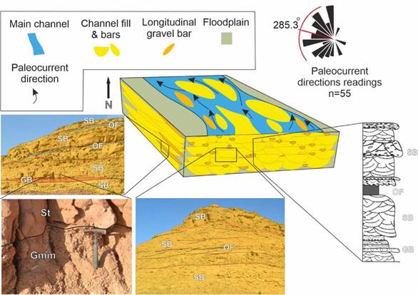
Figure 15 Conceptual depositional model of the study area (not according to scale). The lateral and vertical profiles show sandy bedform elements (SB), gravely bars and bedforms (GB) and overbank fines elements (OF).
4.5 Environment of deposition
The abundance of coarse-to medium-grained sandstones and conglomerates as well as the rare occurrence of fine sandstones, silts, and mudstones indicate deposition in a high-energy stream (Miall, 2006). This is supported by the presence of trough cross-bedded sandstone (St) as the predominant facies. Trough cross-bedding defined by planar or concave-up erosional surfaces in multi-story large-scale sandstone bodies suggests deposition by high-energy streams (Allen, 1983; Miall, 1985). The facies associations found in the study area include those that are described by Miall (1977a) as the most common facies in modern and ancient braided rivers. These facies are matrix-supported massive conglomerate (Gmm), stratified conglomerate (Gt), trough cross-bedded sandstone (St), laminated sandstone (Sl), and horizontally bedded sandstone (Sh). The deposition of these sediments is suggested to have occurred by channel aggradation, as there is no obvious evidence of lateral accretion (Miall, 1977a).
The measured vertical profiles are similar to some extent to the South Saskatchewan type described in Miall (1977b) and Cant (1977). The South Saskatchewan River in Canada is a modern, medium-sized sandy braided river that has cyclic deposits of mainly medium to coarse trough cross-bedded sandstone facies (St) representing channel deposits, with minor sand flat deposits such as parallel laminated sandstone facies (Sl) as shown in Figure 1 of Miall (1977b). The floodplain deposits of that river occur at the top of these deposits but in minor percentages (Cant, 1977). Similar depositional cycles are present in the studied successions, and they typically start with pebbly coarse trough cross-bedded sandstone facies (St) that fines upward and end with massive mudstone facies (Fm) as can be seen in the vertical profiles shown in Figure 5 and the lateral profiles such as in Figure 7A.
Most of the lateral profiles show good lateral continuity of channel deposits, as can be seen in Figure 7A and Figure 10A, which suggests that deposition was mainly under unconfined flow regimes (Kim et al., 2009). One of the characteristic features of braided rivers is the aggradation of channels, and this can be seen in the channel fill elements (CH) at Location 10 in the study area (Fig. 7A; Bristow, 1987). The sandy bedform elements (SB) are interpreted as three-dimensional dunes which are one of the morphological characteristics of braided rivers (Miall, 1977b). Similarly, the longitudinal bars or the gravelly bar elements (GB) are attributed to braided rivers (Miall, 1977b).
The almost complete amalgamation of channel fill facies, mainly composed of trough cross-bedded sandstone facies (St), with very minor overbank deposits suggests lateral migration of channels, and such channel architecture implies the deposition in the proximal zone, near to source area (Nichols and Fisher, 2007). The multi-story channel fill is deposited as a result of channel avulsion and can be attributed to deposition in braided alluvial plains (Tedesco et al., 2010). Sand bars occur creating several channels within the main channel which is characteristic of braided rivers.
The presence of massive sandstone facies (Sm), even though in a low percentage (7%) in this braided system, can be justified by changes in current velocity. Massive mudstone facies (Fm) is also one of the fine-grained facies that can occur in a braided river but in a minor percentage compared to meandering rivers (Miall, 2006). They are interpreted to be deposited during times of floods within floodplains and swamps (Jo and Chough, 2001; Boggs, 2006).
A proposed conceptual paleoenvironmental model for the study area is shown in Figure 15. At the time of deposition of the sediments, the study area was located at the proximal part of a braided river that flowed approximately to the northwest. Whereas the source area is to the southeast. Most braided rivers show longitudinal sand or gravel bars in their main streams (Miall, 1977a). These are symbolized by lenticular bodies within the channels (Fig. 11).
The findings of Oshi (2004) implied that the fluvial deposits of the Shendi-Atbara Basin in Umm Ali area and its vicinity, northeast of the study area (Fig. 2), are distal or non-proximal to their source. Bussert (1988) in his sedimentological studies of Naga area and the adjacent Wadi Awatib concluded that the sediments were deposited in a braided plain, which corroborates the findings in this study. Accordingly, it can be deduced that the lateral variation in facies in the basin from proximal to distal is approximately from the south to the north.
The tectonic activities during the Late Jurassic to Early Cretaceous period introduced major changes in the paleogeography of northeast Africa, including Sudan (Reyment & Dingle, 1987; Fairhead, 1988a). Such events led to the formation of multiple braided fluvial systems in the region (Klitzsch and Squyres, 1990). As mentioned previously, the studied part of the Shendi Formation in Musawwarat-Naga area was deposited by a braided fluvial system. The paleocurrent directions pattern (Fig. 15) has a considerably wide dispersion that might be due to many factors such as deposition time, measurement location, and the nature of the river bars (Selley, 1968; Shukla et al., 1999). However, the major cause of the difference of paleocurrent directions might be attributed to the tectonic activities, such as uplift and subsidence, that prevailed during the formation of Shendi-Atbara Basin and led to changes in the mainstream direction through time (Fairhead, 1988a).
4.6 The implications for hydrocarbon exploration
The majority of the hydrocarbon reservoirs in the sedimentary basins of Sudan are composed primarily of sandstones deposited in proximal fluvial settings (Schull, 1988). Findings from this study, therefore, provide an outcrop equivalent that might aid in studying the paleoenvironment of subsurface reservoirs of these basins. Such analogs can help in enhancing the understanding and prediction of the proximal fluvial depositional style.
The architectural elements recognized in the study area show that the degree of sedimentologic heterogeneity is relatively low as evidenced by the predominance of the channel fill elements (CH) and sandy bedforms elements (SB) as compared to the rare presence of the impermeable rocks represented by the overbank fines elements (OF). On the other hand, the general coarse-grained nature of the studied successions along with the scarcity of feldspars and lithic fragments positively contribute to the quality of a probable reservoir in the subsurface (Taylor et al., 2010).
While the porosity values determined in sandstone thin sections are relatively low (5%-15%) when it comes to reservoir quality, those values are suggested to be affected by diagenetic processes that filled the pores with iron oxides. In the subsurface of the Muglad Basin, iron oxides were found in low percentages in the pores of sandstones in the reservoirs of Ghazal, Zarga and Bentiu formations (Makeen et al., 2021a; Makeen et al., 2021b). However, the porosity of these reservoirs is still relatively good (more than 20%) and this might be a result of other factors such as the dissolution of less stable minerals like feldspars (Makeen et al., 2021b). Therefore, a detailed petrophysical study of the potential subsurface reservoirs will be required to confirm whether the porosity of the sandstones of these reservoirs is affected by iron oxides.
Further research work is also suggested to focus on quantitative facies analysis which is essential for accurate depositional modeling. Furthermore, a detailed three-dimensional (3D) study of the fluvial architecture of the outcrops in this area and other areas in the region should be conducted to characterize the reservoir properties, connectivity, and heterogeneity in detail. Since the characteristics of the reservoirs in the subsurface can be highly similar to the surface analog, such reservoir properties can now be studied in detail from outcrops by digital modeling. Those methods involve three-dimensional aerial photographing (image modeling) and terrestrial laser scanning or ground-based Lidar techniques (e.g., Bellian et al., 2005; Keogh et al., 2007; Zhanfeng et al., 2015; Magalhaes et al., 2017; Siddiqui et al., 2018).
Such studies will help in producing digital outcrop models (DOM) that can be compared with models from the subsurface to perform a reality check (Keogh et al, 2007). As three-dimensional subsurface reservoir geological models represent an integral part of the oil and gas industry (e.g., Radwan, 2022a: Ali et al., 2022), the comparison between outcrop analogs and subsurface models will probably result in more realistic 3D geological models, and can as well help in developing a better understanding of the reservoir properties, geometry, heterogeneity, and connectivity in the subsurface (Keogh et al, 2007). Additionally, such realistic models might be useful in enhancing our flow simulation models in hydrocarbon systems (Bellian et al., 2005).
5. Conclusions
The sedimentology of the outcropping part of the Shendi Formation in Musawwarat-Naga area was studied using facies, architectural and petrographic analysis to deduce the depositional environment and the provenance of the sediments. The identified lithofacies association consists of eight facies with a dominance of trough cross-bedded sandstone (St). The architectural elements identified, which involve sandy bedforms (SB), channel fill (CH), gravelly bars and bedforms (GB), and overbank fines (OF) elements, indicate deposition in a fluvial environment of a braided, proximal setting.
The analyzed sandstones are predominantly quartz arenites. The plot of quartz-feldspar-lithic fragments (QFL) percentages on the ternary diagram showed that the tectonic setting of the sediments is within the craton interior. The provenance is suggested to be the Butana Complex southeast of the study area as evidenced by petrographic results and mean paleocurrent directions of 285.3°.
The low degree of sedimentologic heterogeneity along with the general coarse-grained nature of the studied successions might suggest that a probable subsurface reservoir might be promising. However, the presence of diagenetic products such as the iron oxides might negatively affect the porosity and the permeability of the potential reservoir. Therefore, further research work is recommended to focus on these aspects and to create high-resolution fluvial reservoir analog models for subsurface hydrocarbon exploration as the outcrops in the area are suitable for such a study.


