1. INTRODUCTION
Cable Driven Parallel Robots or CDPR have been widely studied in many areas. For uses such as Contour Crafting [1] to manipulate patients in medical areas [2], these types of robots are versatile in many applications [3]. Therefore, CDPR are ideal for pick and place operations [4] due to their high speeds and large workspaces. Compared to rigid parallel manipulators, cable-driven parallel robots use cables as links instead of rigid ones to control the motion of the end-effector. CDPR provide desirable characteristics, including potential large workspace, the facility to be reconfigured, high speeds of motion, and high payload capacities to weight ratios [5]. Additionally, CDPR with small to very large cable lengths allow them to be stored on spools or drums thus allowing to build robots with a workspace of wide dimension. Depending on their size they may be less expensive, easier to build, reconfigured, safer and non-invasive [6].
The following paper takes a parametric approach on the design process of CDPR, highlighting one of the main advantages of these types of robots that is scalability. In order to validate and foresee possible errors in this approach, a prototype was developed and tested. Subsequently, the paper details the design and construction process for a suspended planar cable robot starting with the relevant mathematical models shown in section 2. Based on the models, a graphic interface was programed to be able to select the actuators needed for any suspended planar robot to be built, making its design parametric. Section 3 shows the interface and the mechanical, electronic and control design and implementation for a built prototype.
Finally, section 4 presents the measurement results of the said prototype’s movements comparing simulations and experimental results in order to validate the design process. Conclusions are shown in the last section for future projects and recommendations for the construction process.
2. MODELS
Within CDPR, different architectures are identified and can be classified according to [7] in the following ways:
According to their degrees of freedom:
Planar: They can move and turn in a single plane (2 dimensions)
Spatial: Allow movement and orientation changes in a three-dimensional space
Depending on the connection between the cables and the end effector:
Suspended: Constructed so that the vertical components of the tensions in the cables are always opposite to the force of gravity
Commanded: A robot is considered commanded when some of the components of the cable tensions go in the same direction as gravity
Depending on the number of cables in the system:
Under-Constrained: When the end effector has infinite positions or orientations for certain lengths of its cables
Fully-constrained: When, through a combination of cable lengths, the end-effector can find only a single position or orientation
Over-Constrained: When a single position or orientation can be reached through different cable configurations.
Mathematical models are defined to study robotic cable systems cables. These models vary depending on the architecture selected. This article focuses on a planar suspended robot and will then expose its relevant mathematical models: Inverse kinematics, static and velocity analysis.
2.1. Inverse kinematics
In a robot, kinematics is defined as the relationship between the position and orientation of its end effector with its articular coordinates [8]. In this way, the inverse kinematics allow to obtain the value to be taken by the actuators to achieve a specific position and orientation of the robot`s end.
In the specific case of the CDPR, the inverse kinematics aim to find the lengths of the cables for a certain position of the end-effector. In Fig. 1, a simplified scheme of the implemented architecture is presented:
Geometric relationships are found between the length of the cables (L1, L2, L3 and L4) and the position of the end effector as shown in the equations found at (1):
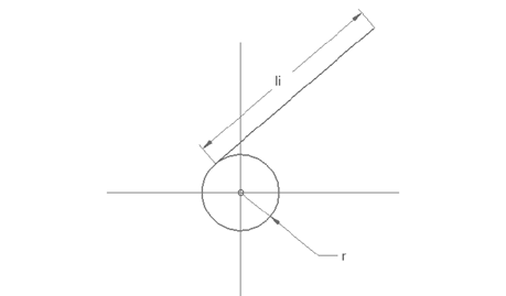
Finally, the lengths with the articular coordinates are related making use of the diagram in Fig. 2 and the equation (2).
2.2. Static analysis
In cable driven parallel robots, the work space is limited, not only by the dimensions of the frame, but also by the tension present in each of the cables in a given instant [3]. Therefore, the workspace area of a CDPR is defined by the space within the frame whose Cartesian coordinates ensure that the tension has a positive value in all of its cables. If α is defined as the set of the points that belong to the workspace, Equation (3) summarizes this definition in the following expression:
When defining Tt i as the sum of tensions on the left side and 𝑇𝑡 𝑑 as the sum of tensions on the right side, the tensions can be simplified using a free body diagram (FBD) as shown in the Fig. 3.
By means of geometric relations, the values for the angles of the tensions can be expressed as in Equation (4).
Establishing equilibrium equations  , the Jacobian matrix (A) can be obtained and the independent term vector (b) shown in Equation (5).
Lastly, to identify the tensions in the cables, the solution for the equation system is described as follows:
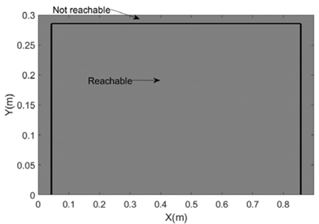
It is then possible to generate the achievable workspace of this type of robots using a computational tool like Matlab ®. The result is shown in Fig. 4.
In reality, there are factors that modify the shape of this workspace; factors such as the minimum tension and the maximum tension allowed by the actuators. The evaluation of the effects of these factors on the workspace are observed in Fig. 5 and Fig. 6 respectively.
2.3. Velocity analysis
For the speed analysis of the robot, the mathematical model used was the inverse Jacobian matrix. This allows to obtain the speeds of the articulations of the Robot (actuators) starting from speeds defined for the edge [8]:
Starting from the equations (1) and (2) that describe the inverse kinematics, they can be derived in time and using eq.(7), the inverse Jacobian matrix is defined as shown in (8).
3. TOOLS AND METHODS
3.1. Parametric design
Based on the mathematical models explained in the previous section, aiming to develop a parametric system, a program was developed in order to select the actuators required for the construction of any CDPR with the mentioned architecture (planar suspended). Specifying needs of space and load of the robot, the interface also needs the following parameters as entrees for the calculus:
Height: Vertical dimension of the desired work space and the end effector in meters.
Payload: Mass in kg to be manipulated by the robot.
Dimension factor: A factor that relates how large the frame in regar• Length: Horizontal dimension of the desired working space and the end effector in meters
ds to the desired workspace of the robot (must be greater than 1)
Minimum tension safety Factor: Percentage of the mass equal to the minimum tension of the robot. This factor guaranties that the tension in the cables is never equal to zero or negative values; therefore, the robot never loses orientation of the end effector.
Pulley Radius: Radius of the pulleys carrying the actuators.
X: presents two spaces to enter the initial and final position of the effector in the x-coordinate, in order to calculate the speeds.
Y: Presents two spaces to enter the initial and final position of the effector in the y-coordinate, in order to calculate the speeds.
T: time to perform the movement established in the previous entries.
As output parameters, the interface is capable of calculating the minimum torque required, the maximum velocities and the power of the motors or actuators needed for the robot. The interface can be seen in Fig. 7:
Using the developed program, actuators were calculated to create a prototype. It was determined that the robot to be built will handle a load of 1 kg and reach maximum vertical speeds of 20 cm/s. So, the input and output parameters are seen in Table 1 and Table 2 respectively:
3.2. Mechanical system
Once the requirements of the actuators are obtained, the characteristics of the chosen motors are seen in Table 3 [9].
Once the actuators were chosen, it was necessary to develop a mechanical system that allowed the cable to be rolled and released. A mechanical system was implemented to ensure that the pulley radius did not change, and the alignment of the cable remained constant. To avoid distorting forces in the end effector movement, a solution was based on [10] and modified to adapt to the specific needs of the prototype.
The mechanism is a threaded drum or pulley, where the cable winds up. This drum spins in a fixed threaded shaft to ensure the same starting point for any instance of time. The details of the adapted mechanism are seen in Fig. 8.
The next elements in the robot's mechanical system are the upper pulleys. These allow the cables to have opposite tensions to gravity, even if the actuators are positioned at ground level. Their design was made in order to eliminate any perpendicular forces to the motion plane of the robot, as well as unwanted output angles. For this reason, they were designed with a minimum thickness so that only a nylon cable could pass between their inner faces (Fig. 9).
Finally, the end effector was designed so that the four cables could be secured ensuring that the distance between cables never changed, as shown in the Fig. 10.
Fig. 11 shows the mechanic assembly of the CDPR.
3.3. Control system
To determine the position of the end effector in the robot, position controllers were tuned for the actuators and a decentralized design was implemented to enable perform synchronous tasks. This meaning, being able to perform movements on both motors simultaneously.
The tuning of these controllers starts with the identification of the system then a controller design process and a final performance evaluation [11].
3.3.1. System identification
To appropriately control the actuators, it is first necessary to identify system dynamics using a transfer function. To avoid the inherent destabilizing dynamics in the position of a dc motor, the angular velocity of the system had to be identified, and then proceed to find the position function, using the expression shown in equation (9).
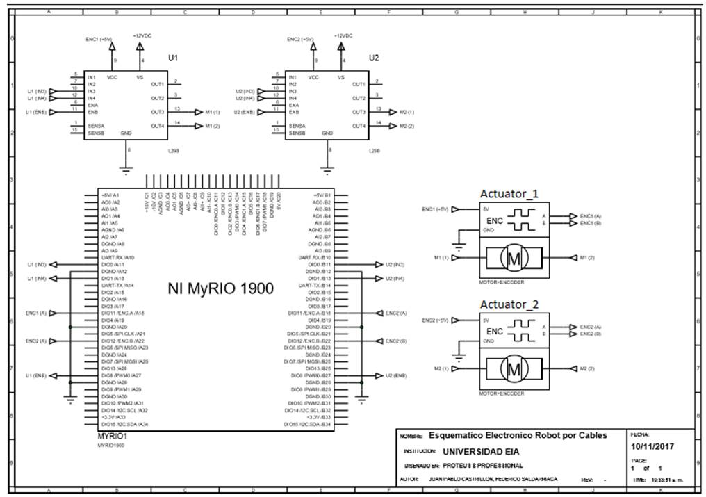
To identify the system, the motor was stimulated using step signals in PWM percentages and the response of its angular velocity was observed using the incremental Quadrature encoder integrated into the motor. For this, a National Instruments MyRIO acquisition board was used [12] and connected to the actuators as shown (Fig. 12).
Source: Authors.
Figure 12 Connection diagram for identification and operation of the DC motors in the CDPR
Equation (10) shows the formula used to determine the angular velocity of the motor using position measuring elements such as quadrature encoders:
It is necessary to mention that this measurement is possible given the good resolution of the encoders and the acquisition board. Otherwise this identification strategy would not be feasible.
The data obtained from the identification experiment is observed in Fig. 13.
The data shown in Fig. 13, was processed using the Matlab® identification toolbox which estimates a transfer function (tf) and evaluates its accuracy or fit using system data. With a fit of 88.61%, the transfer function obtained can be observed in eq. (11).
The parameters given for the identification process were 1 pole and no zeros in order to get the transfer function (11).
The mentioned fit is given by the program and calculated internally by the Matlab® identification toolbox [13].
Once the velocity transfer function was established, it was integrated to the time factor to obtain a position transfer function:
3.3.2. Controller design
Starting 3 main architectures of controllers (PID, PI and PD), these were designed with similar performance parameters to obtain a system with critically damped behavior (ʓ =1). Using a sampling time of T=0.01 and settling times 1.5 and 4 seconds, the best controllers of each type were obtained and are described in Table 4.
3.3.3. Performance evaluation
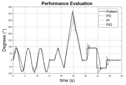
Given the desired settling times and robustness parameters for the tuned controllers [14], a pattern signal was designed (Fig. 14) including sine-type dynamics given their smooth accelerations and ramp-type dynamics in order to obtain constant speeds and step-type references to evaluate their behavior to drastic changes in the reference. This signal tested the three designed controllers (Table 4).
Error metrics were used to evaluate controller performance by means of: ITAE and relative error, related in equations (13) and (14). Table 5 shows the comparison of the results for each controller. It is seen that for both performance parameters the controller PD had the best performance.
Considering the hardware used and its limitations, the error obtained for the PD controller is partially the result of having low specification hardware. Factors such as encoder resolution or gear backlash can greatly affect the controller performance [15]. Improving hardware specifications can resolve smaller errors as shown in [16].
It is important to consider that the error measured for each controller considers both transient and stable state dynamics. It is also generated by trying to follow an ideal trajectory, which represents the most critical conditions possible in terms of speed and acceleration for the robot’s movement and position control system.
3.3.4. Motor synchronization
Because cable driven robots are parallel robots, trajectories of the end effector depend on how synchronized the robot actuators (motors) are. In other words, appropriate and adequate movement of the end effector, the initial and final times for the trajectory of the motors must be as similar as possible. This, not only guarantees the initial and final position of the effector, but also ensures linearity in the trajectories to be performed. To determine dual motor synchronization, an experiment was designed in which, the PD controller was implemented in both actuators and the pattern signal of both motors was measured to compare results.
When measuring actuator behavior, the greatest time mismatch for the step type signals was of 0.2 seconds. An example of this behavior is shown in Fig. 15. This gap is considered acceptable because step signal dynamics will not be present in the robot, because as shown in the next section, soft polynomial trajectories were chosen as reference signals for the system.
3.3.5. Trajectory generation
In order to restrict actuator accelerations and speeds in all points of the trajectory, high order polynomial trajectories were selected [17]. From these trajectories, physical restrictions, precision criteria and softness were then contemplated [8]. Otherwise, "in the polynomial trajectories the degree of the polynomial depends on the number of conditions to be satisfied as well as of the smoothness in the resulting movement" [18] fifth-order trajectories were implemented, like those shown in Fig. 16.
4. RESULTS
The built robot can be seen in Fig. 17.
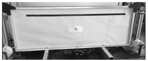
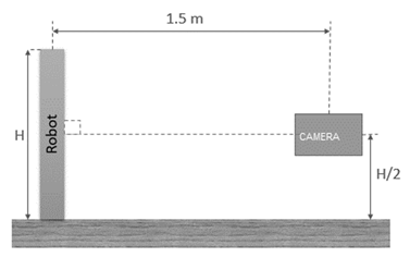
Once built, three Cartesian trajectories were designed to test its operation, which are seen in Fig. 18 through Fig. 20.In order to obtain displacement measurements for the end effector to determine the precision of the prototype, two different measurements were used: first, the trajectories in the motors were simulated without having the robot assembled and with the use of the direct kinematics of the robot, an approximate trajectory of the end effector was produced. Second, with the built robot and using the assembly shown in Fig. 21, a video of the robot`s movement was taken and analyzed with video analysis software. Measuring the end-effector position using computer vision, which has proven to be an adequate method that presents the advantage of demonstrating the effects of certain parameters such as the flexible nature of cables. Simultaneously, because it is an external measurement, system performance is not affected [6]. Tracker software works by measuring an object’s displacement frame by frame to determine the actual movement of the object in the video [19]. This, to point out that the robot was recorded with a 60 FPS and 1080 p. camera.
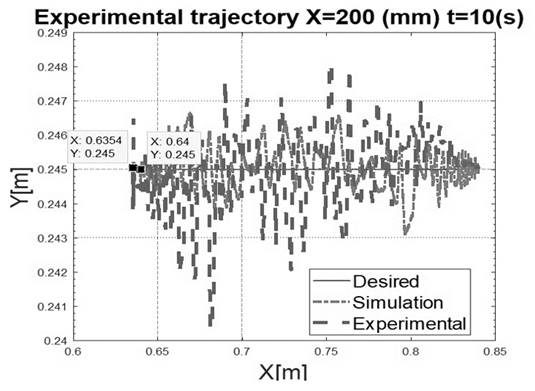
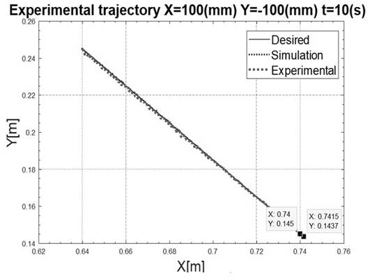
Both results (simulation and real movement), as well as the desired trajectory, are showed in Fig. 22 through Fig. 24:
Source: Authors, 2018.
Figure 22 Desired, simulated and real movement for a horizontal trajectory of 20 cm
Source: Authors.
Figure 23 Desired, simulated and real movement for a diagonal trajectory of equal components (10 cm)
In the previous figures, the blue trajectory is the desired, the red trajectory is the simulated using the encoder measurements and the direct kinematics model and the violet trajectory is measured with the non-invasive proposed method. The previous tests show that the maximum deviation for the built prototype was 3% for the trajectory of 200 mm in X.
Errors can be traced back to many factors of the prototype. On the other hand, hardware limitation influence in controller performance, explained in section 3.3.3, proves there are certain inherent factors in cable driven robot dynamics that can affect the precision and accuracy of the robot. These factors include pulley design, cable properties such as material, elongation and mass, and the estimation of the feasible workspace of the robot [15].
As seen in the previous figures, horizontal movements present more errors than vertical. This can be explained due to fact that the motors are not completely synchronized as shown 3.3.4. This time gap between both motors has greater influences on movements requiring both motors to move in the same direction than on those requiring opposite movements. Also, gravity acts as an orthogonal force in horizontal movements which causes undesired behaviors in the cables.
5. CONCLUSIONS
Regarding the calculation of the robot's workspace, two fundamental factors are derived for its optimization, the minimum tension factor and the maximum tension. Analyzing the complexity of optimizing both parameters simultaneously one can opt to leave one of these parameters as input (fixed) and calibrate the other. Finally, maximum torque was optimized because it was found that the security factor can be personalized according to the application or scenario in which the robot is going to operate.
The maximum torque calculated using the workspace only takes into consideration static effects. This condition restricts the veracity of the calculation and makes it valid for small speeds and accelerations where the dynamic effects are negligible.
When evaluating motor synchronization, the obtained results were considered satisfactory because both motors were adjusted with the design of one controller.
The use of high-order trajectories is fundamental in these types of applications. Ensuring smooth speeds and acceleration curves causes actuators to make low efforts that do not compromise the mechanical design of the robot.
When transitioning from simulations to the prototype, robot precision and accuracy was smaller than in the simulations. This is because the mechanical components of the robot influence the control of the motors causing the actuator not to move in a linear way and have millimetric errors in its Cartesian position. One of these mechanical factors is the backlash between the threaded shaft and the drum of the cable collection mechanism. In addition, it has been shown 7], that changing the shape of the end effector for one that includes fixed pulleys of the same radius as the pulleys of the structure, significantly improves robot movement.


