


 English (pdf)
 Article in xml format
 Article references
 Send this article by e-mail
 Cited by SciELO
  Cited by Google
  Similars in
SciELO
Similars in
SciELO  Similars in Google
 Permalink
1. Introduction
Table 3 Notations
| Notations | |
|---|---|
| a | length of web panel |
| b f | width of flange |
| b st | width of stiffener |
| b 1 | position of longitudinal stiffener |
| D | flexural rigidity of unit width of the web plate 
|
| E | Young’s modulus |
| F cr | critical buckling load |
| F U | Ultimate loads |
| F y | Yielding load according to the Eurocode EC3-Part. 1-5 |
| h w | depth of web panel |
| I st | effective second moment of area of stiffener |
| K F | buckling coefficient |
| k fl | buckling coefficient for longitudinally stiffened plate girders |
| k sl | contribution of a longitudinal stiffener to the buckling coefficient k fl |
| s s | length of patch load or stiff bearing length |
| t f | flange thickness |
| t st | stiffener thickness |
| t w | web thickness |
| ( | flange stiffness parameter 
|
| ( s | relative flexural rigidity of the longitudinal stiffener 
|
| ( t | transition rigidity |
| ( | Poisson’s ratio |
A proper determination of the patch loading resistance of steel plate girders is a typical structural verification that requires attention in steel bridges erected by launching. Occasionally, slender I-girders with considerable web height are used as structural alternatives. These thin-walled webs are frequently reinforced with longitudinal stiffeners to increase bending and shear strengths, and for bridge erected by incremental launching these stiffeners also provide an enhancement for patch loading resistance. Patch loading may generate a localized failure in the web plates in the form of an intertwined mechanism of yielding and buckling often referred to as web folding or web crippling. For the sake of predicting ultimate load capacities of steel plate girders subjected to concentrated loading, researchers have separated the theoretical studies for elastic buckling load F cr and for the ultimate load F U . Ultimate load capacities can be defined by calibrating instability-related resistance functions χ =f(λ), where the slenderness parameter λ =f (F cr , F y ) or by using closed form solutions F U as upper bounds. The former verification procedure is implemented in European provisions [1] whereas the latter is implemented in American provisions [2].
Several studies in the literature have been devoted to investigate cases where the load is fractionally applied over the girder flanges. In particular, for the calculation of F cr , the elastic buckling analysis of both unstiffened and longitudinally stiffened girder webs is a theoretically complex problem due to the large number and range of geometrical parameters involved. Initially, studies on the linear buckling behavior of simply supported plates under compressive loading have been conducted [3-5]. It has been demonstrated that the critical buckling load of simply supported plates increases with the use of longitudinal stiffeners placed adequately [6, 7] Additionally, results using the folded plate theory have shown that a stiffener placed at one-fifth of the girder depth increases considerably the critical load for patch loading [8]. The contribution of flanges on the buckling coefficients for patch loading was also investigated [9].
Later on, an extensive numerical investigation led to the inclusion of the positive effect of longitudinal stiffening into the formulation for buckling coefficients of longitudinally stiffened webs under patch loads [10]. Moreover, numerical analyses have been performed to investigate the rotational restraints provided to the web plates by the flanges in unstiffened webs, developing new formulae for crane girders [11]. A linear buckling analysis was carried out to describe the behavior of unstiffened plates under interacting patch loading and bending moment [12]. Recently, a series of numerical studies were conducted to investigate the elastic buckling of unstiffened and stiffened panels subjected to opposite patch loading for different boundary conditions [13]. Furthermore, factorial design analysis was also employed to examine the influence of several geometric parameters on the buckling coefficient of longitudinal stiffened girder webs [14].
The results from the studies mentioned above can be summarized as follows, the influence of several geometric parameters has been investigated such as: (a) panel aspect ratio; (b) flange stiffness parameter; (c) size of the longitudinal stiffener; and (d) relative position of the stiffener. However, there are still some uncovered issues as for instance, in the patch loading case the available formulae were developed for short loading lengths [15-17]. Some works related to this influence have been presented for ultimate load capacities rather than for elastic critical buckling loads [18-24]. Therefore, this paper aims at investigating the influence of the loading length on the buckling coefficients and transition rigidity for longitudinally stiffened girders subjected to patch loading. Buckling coefficients are computed numerically by means of linear finite element analysis; the patch loading length is varied to cover cases with large loading. These analyses are also conducted for various panel aspect ratios, stiffener positions, and stiffener rigidities. The results show that the buckling coefficient increases with increasing load lengths for certain aspect ratios. Aspect ratios and stiffener rigidities shape these observations to a major extent as described in the following.
2. Numerical model
Figure 1 shows the nomenclature used herein for a longitudinally stiffened girder subjected to patch loading.

According to the classical buckling theory [25-27] , the critical buckling load F cr of a plate is expressed as displayed in Equation (1):

where k F is the buckling coefficient that depends on edge support conditions, on stress type and on the panel aspect ratio of the plate element.
For simplicity, a parameter commonly used to describe the capacity of a stiffener to resist buckling is the flexural rigidity (γ s ) of the stiffener, which can be expressed relative to the plate stiffness as shown in Equation (2):

where D = E t w 3 /12 (1-ν 2 ) is the flexural rigidity of a unit width of the web plate. The second moment of area I st of the longitudinal stiffener is calculated with respect to its centroidal axis parallel to the web plate, for an effective cross section consisting of the stiffener itself and an effective portion of the web plate having a width of 15t w on each side of the stiffener weld [1].
Buckling coefficients are computed herein through eigenvalue analysis using the FE-program ANSYS [28]. Shell elements S181 from the ANSYS element library [28] were used to model the web, flanges (top and bottom) and the longitudinal stiffener. Due to the symmetry in geometry, loading and boundary conditions only one-half of the girder was modeled. Transverse stiffeners at the end of the girder were replaced with kinematic constraints, i.e., displacements in y and z directions, and rotation in x direction were restricted. To model the symmetry, displacement in the x direction, and rotation in y and z directions were restrained [Figure 1]. A patch load was applied by loading all the nodes located in the loaded flange along a loading length equal to s s /2, displacements in the x and z directions, and all rotations were restricted, allowing only vertical displacement in the y direction (following the hypothesis of a stiff bearing length s s ).
For simplicity, a rectangular cross section of the stiffener (flat stiffener) is used in the parametric analysis. The following geometry is used as a basis for the analysis: h w =1000 mm, a =1000 mm, t w =4 mm, t f = 8 mm, b f = 250 mm, b 1 = 200 mm, s s = 200 mm, t st = 3 mm. Figure 2 shows the adopted finite element mesh with 4872 elements after performing a convergence study (see Figure 3]. Additionally, the buckling coefficients are calculated using a Young’s modulus E =210 GPa and Poisson’s ratio ν = 0.3. Table 1 shows a comparison between buckling coefficients computed with the numerical model and those obtained numerically in [10]. It is worth noticing that the buckling coefficients in Table 1 were obtained for a fixed loading length (s s /h w = 0.2). A very good agreement is observed for a panel aspect ratio a/h w = 1.0 with greater but acceptable differences for a/h w = 2.0 and a/h w = 4.0.


3. Parametric study
In the literature, several investigations [10, 11, 13, 14] on buckling coefficients for longitudinally stiffened girder webs have focused their attention on the influence of the panel aspect ratio (a/h w ), relative position of the stiffener (b 1 /h w ), relative flexural rigidity of the stiffener (γ s ), and the load length-to-panel height ratio (s s /h w ). Nevertheless, in most cases the girder height (h w ) has been kept constant while the panel width is increased (a), which leads to the consideration of short loading lengths. Therefore, in order to investigate the influence of the loading length as a more refined parameter, the stiff bearing length-to-panel width ratio (s s /a) was used herein.
In this section, a parametric analysis is conducted in order to evaluate the influence of the following parameters:
Patch loading length was varied s s /a = [0.1, 0.2, 0.3, 0.4, 0.5, 0.6].
Relative position of the stiffener b 1 /h w = [ 0.1, 0.2, 0.3].
Relative flexural rigidity of the stiffener γ s = [0, 14.8, 40.4, 86.2, 158.1, 406.6], corresponding to six values of stiffeners thickness t st =[0, 3, 4, 5, 6, 8] mm.
Panel aspect ratio a/h w = [1, 2, 4].
It is worth mentioning that for the sake of minimizing the influence of the torsional rigidity of the longitudinal stiffener in the studied phenomenon, the width-to-thickness ratio was fixed to b st /t st = 15. Figures 3 to 5 present the buckling coefficients computed for various panel aspect ratios a/h w and loading lengths s s /a, the relationship between the buckling coefficients and the relative flexural rigidity of the stiffeners may be clearly observed. Moreover, the buckling coefficient of longitudinally stiffened girder webs subjected to a fixed patch loading length (s s /h w = 0.2) presented in [10], is calculated using the following expressions:

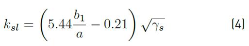

As can be noticed in Equations (3) to (5), the contribution of the stiffener to the critical load depends on the parameter ratio b 1 /a, valid within the range of 0.039 ≤b 1 /a ≤ 0.3 [29]. In the particular case of a/h w = 4 and b 1 /h w = 0.1 (b 1 /a = 0.025) the contribution of the stiffener (k sl ) to the critical load was not considered.
4. Results
4.1 Influence of the bearing length s s /a
Figures 4 to 6 show the results for the buckling coefficients k F in terms of the relative flexural rigidity of the stiffener ( s for various loading lengths s s /a, and the stiffener positions b 1 /h w = 0.1, 0.2 and 0.3. It is clearly observed that the buckling coefficients k F exhibit a bilinear behavior, where k F varies almost linearly for small values of γ s , until reaching a value in which the slope decreases significantly. The corresponding value of ( s at which the slope changes is called the transition rigidity ( t [10]. These results are similar to those obtained previously in [10, 13].
Figure 4 shows the buckling coefficient k F computed in terms of the relative flexural rigidity γ s for various loading lengths s s /a, with a panel aspect ratio a/h w = 1. Meanwhile, Figure 5 displays the corresponding values for a/h w = 2. In both cases, the buckling coefficients increase proportionally with the relative position of the stiffener for aspect ratios a/h w = 1 and 2, and a maximum value for the buckling coefficient is achieved when stiffener is placed at b 1 /h w = 0.3. Conversely, Figure 6 shows the results for a/h w = 4 in which however, the buckling coefficient remains rather constant with respect to the stiffener position. In all cases, the buckling coefficients increase with the bearing length.
It is worth noticing that for small panel aspect ratio (a/h w = 1) and a relative position b 1 /h w ≤0.2, k F values obtained with Equation 3, and based on the relative flexural rigidity restriction given in Equation 5, show a close agreement with numerical values for small patch loading length (from s s /a =0.1 to 0.2). However, for medium or large panel aspect ratios (a/h w = 2 and 4) the buckling coefficients obtained with Equation (3) are lower compared to those computed numerically herein.


In addition to the influence of the position of the stiffener, the variation of the buckling coefficient is also related to the load length s s Figure 7 displays values of k F in terms of s s /a for various relative flexural rigidities γ s =14.8, 80.6 and 158.1 at which the influence of the aspect ratio is also studied. For the a/h w = 1 (see Figures 7a to 7c) there is a nonlinear increment of buckling coefficients as s s /a is increased, while for the other cases a/h w = 2 and a/h w = 4 the increment is rather linear [Figures 7d to7i).
At the same time, another noticeable effect is present when the aspect ratio is a/h w = 4, Figures 7g to 7i show that for any particular value of s s /a, there is no influence of the relative position of the longitudinal stiffener on the buckling coefficient (these elements experience global buckling).

4.2 Transition rigidities
As mentioned above, transition rigidities γ t provide a limit in the k F versus γ s curves. The values of the transition rigidities are calculated by intersecting two straight lines obtained through linear regression. A first straight line that captures the rapid increases of k F with respect to γ s and a second one that describe the slightly increase of k F vs. γ s . With, γ t determined as the intersection point of the two straight lines. Table 2 shows the results of transition rigidity γ t for each calculation; these values remain constant for a patch loading length s s /a. For panel aspect ratios a/h w = 1 and a/h w = 2 the transition rigidity γ t decreases for an increasing stiffener position b 1 /h w . This means that according to the position, the transition rigidity of the stiffener varies. In both cases, the variation of γ t with b 1 /h w follows a different trend. For a/h w = 1 the results can be compared with those found in [10] where the reduction of γ t tends to decrease to a value equal to γ t =15 for a relative position of b 1 /h w = 0.3. In the case of a/h w = 2 the transition rigidity decrease linearly, nevertheless a difference of 37% with the Equation (5) is found when the stiffener is placed at b 1 /h w = 0.3. On the other hand, for a/h w = 4 the results are similar to those obtained in [10], where the transition rigidity γ t is higher than the relative flexural rigidity ( s within the evaluated range.

4.3 Buckling shapes
For the sake of visual inspection, Figures 8 to 10 display isometric views of the buckled shapes for three selected conditions for each case (a/h w = 1, 2 and 4, respectively). Three buckled shapes were obtained for a stiffener placed at b 1 /h w = 0.2, with γ s =158.1. For panel aspect ratios a/h w = 1 and 2, this rigidity is larger than the corresponding transition rigidity (γ s >( t ). A closer inspection of the eigenmodes shows a larger wavelength in the lower panel for an increasing load length ratio s s /a. All cases show an eigenmode that involves buckling in the lower sub-panel.

Figure 8 Buckling shapes for plate girders with various loading lengths (a/h w = 1; b 1 /h w = 0.2; β = 2; γ s =158.1)

Figure 9 Buckling shapes for plate girders with various loading lengths (a/h w = 2; b 1 /h w = 0.2; β = 2; γ s =158.1)

Figure 10 Buckling shapes for plate girders with various loading lengths (a/h w = 4; b 1 /h w = 0.2; β = 2; γ s =158.1)
Noticeably, as shown in Figures 8 to 10, the buckling shapes are affected by the panel aspect ratio. The buckled region tends to be greater for a larger load length as well as for a wider panel. Moreover, for large panel aspect ratios a/h w =4 (see Figure 10c), there is an overall buckling mode of the web panel, in which web and longitudinal stiffener buckle together.
Summarizing, Figure 11 shows the buckling modes for the values of a/h w and s s /a analyzed herein. All modes are extracted in the form of the cross-sectional eigenmode at mid-span. It can be observed that the buckling mode in the center of the girder varies only with the aspect ratio instead of the load length. This variation can be observed when the aspect ratio increases as well as the deformation of the web panel. It is worth noticing that for a panel with a/h w = 4, the longitudinal stiffeners do not provide a stiff nodal line.

5. Conclusions
The influence of the bearing length on the critical buckling load of girders subjected to patch loading has been analyzed numerically with a broad perspective herein. The effect of s s /a coupled with many other parameters such as the aspect ratio of the panel, the position, and second moment of area of the stiffeners show the following conclusions:
Generally, the critical buckling load of the plates increase with s s /a. The effect is particularly observable in stiffened plates with low aspect ratio a/h w = 1 in which the eigenmode is clearly associated with failure of the bottom panel of the directly loaded plate. In these cases, increasing s s /a implies a considerable increment of the buckling coefficient following a nonlinear trend.
For stiffened girders with a/h w = 4, the influence of s s /a is similar (increasing the buckling coefficient with the loading length) but in this case, the enhancement is smaller. Since the panels are considerably wide, the eigenmode partially involves the longitudinal stiffener and the transverse stiffeners do not contribute to the anchorage of such elements.
These conclusions are necessary to point out when it comes to the design of plate girders subjected to patch loading. These elements are often designed with largely spaced transverse stiffeners and less frequently with closely spaced stiffeners. Since the launching shoes generally present standard dimensions available in the industry (1.0 to 2.0 meters), the proportion s s /a will be determined by the binomial decision of the transverse stiffener spacing and the utilized launching equipment. The resistance of webs to concentrated loads will benefit in the case of closely spaced transverse stiffeners and/or large launching shoes since coupled mechanisms involving the transverse and longitudinal reinforcements will determine the load bearing capacity of the plate girder as whole.
Finally, it is recommended to study these complex coupled resistant mechanisms not only from the critical buckling load perspective but also at ultimate load capacity levels.

