


 English (pdf)
 Article in xml format
 Article references
 Send this article by e-mail
 Cited by SciELO
  Cited by Google
  Similars in
SciELO
Similars in
SciELO  Similars in Google
 Permalink
1. Introduction
The constituent elements of machines, equipment or instruments are subject to different types of physical and/or chemical phenomena (e.g., corrosion, high temperatures, contact loads, and fatigue) that can lead to a gradual loss of their functional integrity through degradation processes, which usually start at the surface.
In this context, a surface should be seen not as an ideal and theoretically dimensionless entity that defines and limits a rigid solid [1], but as a complex region [2], or interface, of a few molecular diameters with physical and chemical properties (e.g., microstructure, chemical composition) that behaves differently from the substrate material to which it belongs.
With the aim of ensuring the functional integrity of the surface, different metallurgical and chemical processes, such as the intentional addition or development of surface coatings [3], have been developed. These processes can improve properties such as the corrosion resistance.
Among the methods that involve the addition of a new layer, the capacity to generate electroplated hard chromium coatings is of great importance at the industrial level because of their high hardness (approximately 12.2 GPa), which can increase the useful life of the building elements of machinery, equipment, and tools by maintaining the dimensions of the damaged parts.
However, this type of coating presents a number of limitations that decrease its functional capacity, and hence that of the substrate, which are related to the microcracks caused by the relief of internal stresses produced during the deposition process, with adverse effects such as decreases in the hardness, the wear resistance, and the corrosion resistance, and by greater diffusion of oxidizing agents to the substrate at operating temperatures above 623 K, through the defects mentioned above, with decreased resistance to corrosion [4][5][6].

To overcome the disadvantages of simple surface treatments, such as those mentioned above, duplex treatments have been developed [7][8] that allow a surface to have, in a combined and complementary way, the properties that each of these methods provides individually.
This paper shows the effect of the production of chromium nitride compounds on the corrosion resistance of a hard electroplated chromium coating applied to AISI H13 steel through surface modification by means of a thermochemical treatment of gaseous nitriding in a vacuum, using N2 as a precursor gas.
2. Experimental Procedure
2.1 Materials and Electroplating
The specimens were obtained from an AISI H13 steel bar of 25.4 mm (1 inch) in diameter, with a final thickness of 1.5 ± 0.2 mm, rectified and finished with 600 grit. In this state, the samples were subjected to an electroplating process. The hard chromium coating [Cr(VI)] was applied in a standard electroplated bath (Sargent bath) according to the composition shown in Table 1, with a temperature of 318 K, a cathodic current density of 30 A/dm2, and a plating time of 80 min. The bath parameters were established according to the Standard Guide for Engineering Chromium Electroplating B177/B177M [9].
2.2 Vacuum Gas Nitriding
A thermochemical treatment of gaseous nitriding in a vacuum was performed in order to chemically and microstructurally transform the electroplated chromium coating and thus improve its properties, such as its corrosion resistance, due to the formation of chromium nitrides. Before placing the samples in the treatment furnace, they were subjected to ultrasonic cleaning with an initial degreasing with acetone RG AR and a subsequent rinsing with 2-propanol RG AR, with one min for each phase. The final drying was performed with nitrogen. The gas nitriding process was performed in a furnace built for that purpose. Nitrogen was used as the nitriding agent, with a 100 ml/min of flow, a vacuum pressure of 1.2 kPa, a nitriding temperature of 1343 K, and nitriding times of 6, 8, 10 and 12 hours.
2.3 Existing Phases
The study of the existing phases and their corresponding crystal orientations was performed via X-ray diffraction (XRD). For this purpose, a PANalytical X-PertPro System in Bragg-Brentano mode was used with CuKα monochromatic radiation at a wavelength of 1.540998 Å.
The measurements were performed for diffraction angles of 26 between 20° and 90°.
2.4 Corrosion Testing
To evaluate the corrosion resistance of the nitrided samples, both potentiodynamic polarization and electrochemical impedance spectroscopy (EIS) tests were performed in a Gamry Ref. 600 (660-06060) potentiostat/galvanostat The data capture was performed with Gamry Framework 5.61 V 2010 software. A three-electrode electroplated cell with a saturated calomel reference electrode and a graphite counter electrode immersed in a 3% aqueous solution of NaCl was used at room temperature.
The evaluation of the corrosion resistance via the potentiodynamic polarization technique was performed with a scan rate of 0.5 mV/s and a sampling period of one (1) second, with an initial potential of -0.5 V, a final corrosion potential of 0.7 V, and a sample/electroplated solution contact area of 0,196 cm2. The electrochemical impedance spectra, EIS, were obtained by varying the frequency between 100000 Hz and 0.01 Hz with a data density of 10 dots/decade and an electrolyte/sample of contact area of 0.196 cm2. Measurements were conducted for times of 1, 24, 48, 72 and 168 hours. Before the first measurement, the samples were placed in the electrochemical cell and stabilized in contact with the electrolyte solution for 45 min to establish the free corrosion potential, Ecorr.
3. Results and Discussion
3.1 Study of the phases present
Figure 1 shows the XRD diffraction patterns obtained from the AISI H13 electroplated hard chromium samples nitrided with N2 at 1343 K for 6, 8, 10 and 12 hours. There is no evidence of crystalline chromium present in the nitrided samples, which suggests surface transformation into chromium nitride, as shown in [10] and as is reported by [11] and [12]. Neither were diffraction peaks corresponding to the ferrous substrate (AISI H13 steel) observed. The diffraction peaks observed mainly correspond to Cr2N phase crystallographic planes (111) 2θ: 42,611°, (201) 2θ: 48,137°, and (300) 2θ: 67,349°.
The intensity of the diffraction peaks for the CrN phase was found to be low, and this phase tends to dissolve with increasing nitriding time, favoring the existence of the Cr2N phase only. This is consistent with the results reported by [6] for treatments performed at temperatures above 1273 K. All XRD results showed the formation of a high intensity peak corresponding to the Cr2N phase for the crystallographic plane (300). This result is consistent with that reported by [13] for this phase, after conducting nitriding treatments.

Figure 1 Diffraction patterns of AISI H13 electroplated hard chromium samples nitrided in a gaseous atmosphere in vacuum with N2. T: 1343 K, nitriding times: 6, 8, 10 and 12 hours. Key: a. Cr2N (111) (201) (112) (300) (113) b. CrN (110) (002) (201) (130) (022) c. CrO3 (322) (402) d. Cr2O3 (006) (113) (202) (024) (214) (101) (306) (312).
Furthermore, in studies related to the growth mechanisms of chromium nitride films deposited via vacuum arc deposition with N2 as nitrogen precursor gas [14] [15], the same orientation has been observed in the Cr2N phase for the same crystallographic plane (300) in treatments performed at a partial pressure of 0.5 Pa N2. This orientation attaches to the content of nitrogen in the film, and it can be concluded that the structure and the texturing depend on the nitrogen precursor species, its energy, and the substrate temperature.
3.2 Corrosion Study
3.2.1 Potentiodynamic Polarization
Figure 2 shows the results of this assay for the metallurgical system AISI H13/electroplated Cr(VI) nitrided with N2. To compare the behavior of the nitrided samples, the results of tests performed with this technique, both for the uncoated AISI H13 and for the electroplated AISI H13 without nitriding treatment, were included.
For the uncoated steel, a corrosion current density of 1072.5 nA with a corrosion potential of -0.6148 V was found, while the chromium electroplated steel without nitriding showed a slight improvement in these values (1023.2 nA and -0.5465 V).

This improvement can be attributed to the greater resistance of this type of coating against corrosion. This result is consistent with other studies [5]. A significant change in improving Ecorr values was found compared to the AISI H13 steel and the AISI H13 chromium electroplated steel, which reached values from -0.1175 V to 0.0329 V.
Furthermore, except for the treatment performed for 6 hours, the Ecorr values exhibited better behavior in comparison with both the uncoated (AISI H13) steel and the chrome plated steel. Similarly, the corrosion current Icorr showed a variation between 30.1 and 3.7 nA in the nitriding treatment with N2 compared with the corrosion currents found for the AISI H13 steel and the coating of untreated chromium, respectively. The electrochemical results show a clear definition of active versus passive zones, which can determine the kinetic parameters for establishing the instantaneous corrosion rate of the coatings and the substrate. Likewise, the corrosion potential of the coatings is more positive, indicating a greater thermodynamic resistance to the startup of the corrosion process. The same trend can be observed for the corrosion current density, so that the graphs related to the coatings are displaced towards the left.
2.2 Electrochemical Impedance Spectroscopy
Figure 3 shows the Bode plots for log (frequency) versus log (Zmod) impedance and log (frequency) versus Zphz(°) phase angle for uncoated AISI H13 steel (Figure 4a) and AISI H13 chromium electroplated steel without nitriding treatment (Figure 4b).
The impedance values for the steel coated by chromium electroplating are superior to those obtained for the uncoated steel. Furthermore, the diagram of phase angle versus frequency, shows a time constant for the untreated steel and two time constants for the coated steel (16), which correspond to the nitrided layer and the chromium coating. The transitional phenomena of interaction of the electrolyte solution on the surface are present in the nitrided layer and in the interface with the untransformed electroplated chromium, as well as a marked variation of the phase angle for low frequencies in the diagrams frecuency versus Impedance.
The EIS results for the nitrided samples (Figure 4) show a significant increase in the impedance values at low frequencies (10-2 Hz) for all nitriding times (6, 8, 10 and 12 hours), with orders of up to 107 Ohm/cm2 higher than those found in the chromed sample without nitriding treatment (Figure 4b). This fact could be related to the formation of chromium nitrides of type Cr2N, whose presence was established in the characterization by XRD. Furthermore, it can be seen that the microcracks are sealed by the formation of this phase, as demonstrated by the SEM results (Figure 5), thereby restricting the flow of corrosive agents in the system and increasing the performance of the noble coating.
For low frequencies there are processes occurring at the metal/coating interface that provide resistance to the polarization system and represent the dielectric properties of coating films and the passivity in the pores [16] [17]. The region of the graphic associated with low frequencies is related to processes occurring at the metal/coating interface, which provide the polarization resistance of the system and represent the dielectric properties of the coating and the passivated film in the pores [16] [17], namely,

Here Rp: polarization resistance, Rpo: pore resistance.
Based on the above equation, one can establish that the step of the impedance values of 104 Ohm/cm2 chrome for steels without nitriding treatment up to 107 Ohm/cm2 for nitrided samples due to an increase in the polarization resistance of the system results in the accumulation of corrosion products in defects, such as pores, holes and/or microcracks, in the surface layer of the electroplated chromium coating and the formation of compounds such as CrxN during the nitriding process through the reaction of the chromium plating with the nascent nitrogen product of the dissociation of ammonia and the sealing of the microcracks of the coating through the formation of chromium nitrides..
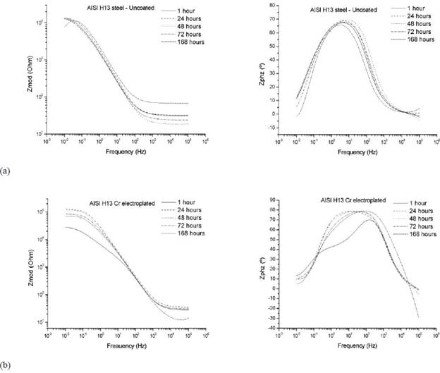
Figure 3 Electrochemical impedance spectroscopy results for (a) AISI H13 uncoated steel and (b) AISI H13 chromium electroplated steel without nitriding treatment.

Figure 4 Bode plots for EIS data of AISI H13 steel samples plated and nitrided with N2, treatment temperature: 1343 K. Nitriding times (a) 6 hours (b) 8 hours (c) 10 hours (d) 12 hours (experimental results).
In the diagram, the curve of log (frequency) versus Zphz (°) phase angle shows the presence of two time constants. The frequency range in which they arise corresponds to a decrease in the impedance values of the system, as shown in the figures for log (frequency) versus log (Zmod).
One of these constants is related to the dielectric properties of the coating at high frequency and the other is related to the electrochemical phenomena at the interface of the nitrided layer and the substrate of untransformed electroplated chromium [18] [19]. In this way, the resistance to the charge transfer is affected by both the nitrided layer and the chromium electroplating [16].
To establish the corrosion parameters, the data obtained from EIS were modeled by an equivalent electrical circuit. Various investigations and studies [16] [20] [21] [22] have demonstrated an applicable circuit pattern for metallic substrates to which a coating has been applied, as shown in Figure 6.
One RC pair is associated with the corrosion process, and the other RC pair corresponds to the coating. In this circuit, Rsol is the resistance of the solution, which lies between the reference electrode and the working electrode surface, and Rpore is the resistance to charge transfer, which is related to the porosity of the coating and exists because of the formation of ionic conductive paths through it. Cc is the capacitance associated with this resistance [23], Rcoat is the resistance to the charge transfer at the substrate/coating interface, where corrosion occurs, and Cdl is the capacitance.

Figure 6 Equivalent circuit model for the adjustment of the impedance spectra for electroplated metal coatings (adapted from [16] and [20]).

Figure 7 Equivalent circuit model for the adjustment of the impedance spectra for the electroplated metal coating with constant phase elements (adapted from [16] and [20]).
The presence of Rcoat is explained by the penetration of the electrolyte through the pores and holes present in the coating. To make adjustments for higher quality data, the capacitances are replaced by constant phase elements (constant phase elements - CPE) that consider deviations from the ideal dielectric behavior associated with surface heterogeneity [17] [20], as shown in Figure 7.
According to [20], for a CPE, impedance can be defined as

Where Z o = parameters for the independent adjustment of the frequency, ω = angular frequency, and n = CPE power, which takes values between 0.5 and 1.0.
If n = 0.5, the CPE represents the Warburg impedance W with a diffusive character. Low values for n are related to the roughness of the coating [20]. If n = 1, the CPE is reduced to an ideal capacitor, whereas if it defaults to 0, it is reduced to a resistance [24]. The Bode plots (Figure 5) show the existence of two time constants.
Table 2 Values for the equivalent circuit parameters for the different samples that were nitrided with N2 and tested with EIS.

One constant is for high frequencies and represents the pattern of the dielectric coating (CPEc and m), and the other constant is for low frequencies and represents the coating/substrate interface properties (CPEdl and n) [16] [17].
The coated metal impedance changes by several orders of magnitude and varies between Rsol for higher frequency values and Rpor + Rp = Rct for lower frequencies [23]. Thus, according to [17], the intrinsic existence of pores in the nitrided layer for the particular case of the thermochemically treated samples further includes the presence of microcracks characteristic of electroplated chromium. Furthermore, according to [16], the high frequency regions are related to the presence of surface defects, with the local frequency of half of the processes indicated in the film or nitrided layer and the low frequency interface processes on the metal/coating. Table 2 lists the values of the equivalent circuit parameters for the different nitride samples tested with EIS.
A comparison of these results with those obtained with the sample nitrided with N2 shows an improvement in the various parameters analyzed, with maximum values of Rcoat on the order of 107 Ohm/cm2 for treatments at T: 1343 K / 6 and 8 hours and no Rcoat values less than 106 Ohm/cm2. The results also show a significant increase in Rpor, which varies between on the order of 103 Ohm/cm2 for T: 1343 K/6 hours and 105 Ohm/cm2 for T: 1343 ° K/10 hours. For T: 1343 ° K/12 hours, although Rpor increases with exposure time, its value is less than those mentioned above. Similarly, for CPE, n and m appeared stable, based on n values from 0.71 to 0.85, incrementally associated with the obstruction of the passage of the electrolyte by sealing the microcracks as a layer on the surface of the electroplated chromium. For m values from 0.87 to 0.99, the increase is related to the increase in the processing variable values, and the exposure times and could be associated with an improvement in the dielectric characteristics of the passive layer because of a decrease of diffusion phenomena through the passive layer.
Figure 8 shows the behavior of Rp for samples treated with nitrogen versus immersion times. The highest values of Rp are found for lower immersion times, which decrease with an increase up to 168 hours. However, insofar as it increases the temperature of nitriding, Rp increases and tends to show a constant behavior with the immersion time. This behavior is consistent with the analysis obtained for the frequency plotted against the impedance and phase angle due to the electrochemical and diffusive phenomena indicated. Treatments with nitrogen lead to a greater Rp and a stable behavior at different times of immersion. All the results above show the possible presence of compounds, where CrxN exhibits a noble behavior and seals the microcracks in the electroplated chromium coating as well as acting as a barrier to the flow of corrosive metal within the system.

4. Conclusions
In this study, a duplex treatment combined the application of a hard Cr(VI) chromium plating on a ferrous substrate (AISI H13) with subsequent surface modification via a thermochemical treatment of gaseous nitriding in a vacuum atmosphere enriched with N2 as a nitrogen precursor. This treatment facilitated the microstructural and chemical transformation (surface and subsurface) of the Cr(VI) electroplated coating to chromium nitride phases of the type CrxN.
The presence of these types of compounds (nitrides) on the surface improved properties such as the corrosion resistance of the chromium electroplating. The presence of the phase Cr2N was determined by means of X-ray diffraction, along with the presence of certain nitrogen compounds and chromium oxides associated with the possible presence of oxygen in the treatment chamber because of the low vacuum. Texturing was found for all special treatments in the crystal plane (300) for the Cr2N phase, which can be explained by the partial pressure of nitrogen, which thermodynamically favored this behavior. Only the Cr2N phase was obtained, which is a phenomenon that is related to the treatment temperature (1343 ° K).
There was a significant improvement in the corrosion resistance of the nitrided samples, as evidenced by the results of potentiodynamic polarization, which led to increases in the magnitude of Ecorr and a decrease in the related values of Icorr. Likewise, the electrochemical behavior of the metallurgic system is favored in the nitriding process, as shown by the substantial improvement in the impedance values and the phase angle in the treated samples, both for the product passivation process and for the sealing of characteristic microcracks of the chromium plating with chromium nitrides.

