


 English (pdf)
 Article in xml format
 Article references
 Send this article by e-mail
 Cited by SciELO
  Cited by Google
  Similars in
SciELO
Similars in
SciELO  Similars in Google
 Permalink
1. Introduction
Several energy conversion processes result in thermal losses, and through thermoelectricity there is the possibility of direct conversion of thermal energy into electrical energy [1]. The generation of energy using thermoelectric materials has no moving parts, being silent, customizable, and reliable. Besides being a non-polluting, renewable generation source that allows the increase of the energy efficiency of equipment using waste heat [1].
Among the possible applications, the incorporation of thermoelectric generators in automobiles has become a viable alternative for increasing efficiency, especially in combustion vehicles, where losses can reach 62%[2].
Research has been conducted to this end since the 1960s [3]., and it is estimated that thermoelectric generators can increase the efficiency of an automobile by up to 8% [2].
Despite the advances, in general, devices for the utilization of automotive waste heat are composed of heat exchangers and heat-pipes, which have the advantage of demanding less heat exchange area and allowing the installation of TEGs in locations other than exhaust duct surfaces [4]. These systems have the disadvantage of high cost, however, and in the case of heat-pipes, the pronounced increase in heat transfer can lead to increased internal pressure, which can even cause the device to rupture. In such cases, increasing the capacity of the system can mean further increasing its cost [4].
In this sense, the present research presents a proposal for a thermoelectric generator, incorporated into the exhaust gas system, of less complexity and easily adaptable to any combustion vehicle. It begins with the state of the art highlighting the research contribution, drawings and schematics of the proposed system. Next, we proceed with modeling the TWHRS using as a basis the numerical model of the thermoelectric module developed in recent research to evaluate its behavior under a set of boundary conditions incorporated into the TWHRS heat transfer system [5-11].
2. State of the art
Recently, studies have been developed in order to take advantage of the temperature gradient between the human body and the ambient air to generate electrical energy to power electronic devices called "wearables" such as Seiko's wrist watches [12],and the thermoelectric bracelet developed by Bastos [13].
As for the integration of TEG with alternative sources, there has been research on the development of hybrid cells (photovoltaic and thermoelectric) that generate electricity from the heat produced by the photovoltaic cells from the Seebeck effect, maximizing the overall efficiency of the system [14].Another route has also been studied to increase the efficiency of photovoltaic cells by using the Peltier effect to cool the cell [15].In addition, the use of thermoelectricity to harness geothermal energy has been studied [16].
Already in industrial applications efforts to harness waste heat in high-temperature industrial furnaces[17],.in municipal solid waste incineration [18], and in diesel cogeneration [19] predominate.
NASA pioneered the use of thermoelectric generators in several space missions. Due to the need to reduce vehicle loads and efficiently harness the energy supply, thermoelectric generators are used in radioisotope nuclear reactors, known as RTGs [20].
In the automotive industry the first TEG applied to automobiles was reported by Neild, et al. in 1963 [21]. In 1988 Birkholz, et al. [22], published the results of their research developed in partnership with Porsche [22] In the 2000s several companies such as GM, BMW, Daimler, Ford, Renault, Honda, Toyota, Hyundai, among others built and tested their prototypes [23].
Currently, there are studies using thermoelectric modules in cars whose combustion engines have a maximum efficiency of 33%, with thermal losses of at least 62%, as shown in Fig. 1, [2].

Source: The authors
Figure 1 Demonstration of the Efficiency and Losses in the combustion process of an automobile.
Considering the temperature gradient between the exhaust, which carries the exhaust gases at high temperature, and the surroundings of the vehicle, it is possible to obtain an increase in the overall efficiency of the car of 8.67% [2].
Many authors discuss the possibilities of installing waste heat utilization systems in hybrid vehicles by installing a heat exchanger containing TEG's [24].
Furthermore, according to research in intellectual property databases, many patent applications have been filed regarding cooling systems, waste heat utilization in industrial applications, material manufacturing processes, solar systems, and autonomous devices [22-26].
Systems applied to automobiles include cooling and temperature control systems for electric vehicle batteries, and automotive climate control systems, which can even be powered by solar panels [27-31].
About generation from exhaust gases they include BASF from Germany [25] and Valeo Systemes Thermiques from France [26]. Notably, the prototypes developed by Hi-Z and Hyundai include heat exchangers with cooling fluids circulating on the cold side of the TEGs, as shown in Fig. 3, [34-36].
Besides those mentioned above there are other prototypes that include the system developed by Hyundai in partnership with Kia Motors, where the thermoelectric generator is embedded in a combustion engine recovering part of the waste heat [27].
The analysis of thermoelectric generation systems can be evaluated from Finite Element Method (FEM) analyses where the effect of thermal and electrical variables can be combined with fluid flow analysis as seen in [28-30].
Finally, the financial and operational parameters were configured. A system capacity of 99,900 kW, a capital cost of 5000 USD/KW, and a fixed operating cost (annual) of 66 US/kW were sized. For the calculation of the LCOE (Levelized Cost of energy), 25-year financing was assumed with a rate of 2.5% per year and a nominal internal rate of return of 13% per year.
3. Proposed system - TWHR
The TWHRS is a system capable of generating electricity from the heat provided by the exhaust gases passing through the rear muffler of the car. Where the average temperature available in the exhaust system is 300°C (Fig. 2). For this, a hexagonal configuration is designed for the muffler, without compromising its operation and that the area can be increased to add the largest quantity of thermoelectric modules.

The TWHRS is composed of new geometry for the automobile's muffler in hexagonal shape so that it is possible to take advantage of its external walls to make the TWHRS.
The hexagonal section is already known as verified in thermoelectric generators from Hi-Z [31] and Hyundai [32]. The advantages of this type of configuration is that it allows the use of conventional thermoelectric modules, which are mostly rigid and have a rectangular geometry with flat faces. This feature also allows the adaptation to different types of thermoelectric modules, making it possible to vary the system for a wide range of modules and materials according to the system's needs.
In each face of the TWHRS are coupled 4 thermoelectric modules (TEHP-1263-1.5) of 3x3 cm, connected electrically in series and thermally in parallel, totalizing 24 modules. While, on the cold side of each thermoelectric module are coupled fin heat sinks made of aluminum, over which air at room temperature flows, increasing heat transfer and contributing to the maintenance of the temperature gradient.
As can be seen in the Fig. 2, hot gases enter the device and release heat through the side walls. While, the thermoelectric modules are subjected to a gradient, as on the outer face, a flow of room temperature air flows over each heat sink. While Fig. 3 shows a three-dimensional drawing of the proposed system.

Source: The authors
Figure 3 Three-dimensional drawing of TWHRS: (a) isometric view, (b) front view (c) side view.
According to the state of the art and the research in the intellectual property registration database, it can be stated that the TWHRS proposal differs from the others by its adaptability, since it can be installed in any car, without the need for major modifications, simply by changing the muffler. It is emphasized that TWRHS also presents the following advantages: (i) Air cooling system: the use of a forced convection mechanism from ambient air presents less complexity, requires no extra components for circulation, and demands less frequent maintenance; (ii) Simplified arrangement: the system has a lower cost because it requires less material to make the heat sink; (iii) Less weight: Due to the use of fewer components, the system has a lower weight, imposing less load on the structure of the exhaust system; (iv) Fuel economy: the generation of additional electric power implies directly in fuel savings and increase of the car's global efficiency; and (v) Reduction of atmospheric pollution: as a consequence of fuel savings, generation through the thermoelectric effect reduces the emission of greenhouse gases and atmospheric pollutants.
Finally, we point out that the TWHRS can be adapted to any situation where there are thermal losses in combustion gases, including in other parts of the exhaust system, if there is a temperature gradient between the internal and external air flows.
4. Modeling and performance of TWHRS
Using as base the modeling of the thermoelectric module presented in [5] that uses: (i) Geometric model developed is a representation of the thermoelectric module model TEHP 1263-1.5, produced by the ThermomamicTM company [33]; (ii) Supported by the literature [34], to reduce the computational effort, where the voltage generated in the thermoelectric module is proportional to the number of p-n pairs, this proposition is used, opting to develop a model with 28 p-n pairs and extrapolate its results to the number of pairs of the real module, that is, 126 pairs; (iii) Modeling of contact thermal resistances is based on the study by Grujicic et al. where they investigate the effect of contact thermal resistance on a CPU [35] and and (iv) According to Bjørk et al, in a TEG the internal heat losses by convection are not significant, however, the radiation losses become significant as the temperature increases because the radiation heat transfer is proportional to T4 [36].
Based on the model proposed in [5], it is possible to estimate the electric power generation of a thermoelectric generator applied to the exhaust gas system of combustion vehicles.
In this research, the study of Hi-Z Inc. [3] and considers a homogeneous temperature distribution on the duct face, so that it becomes unnecessary to evaluate the spatial variation of the gas temperature inside the duct. Note that this is an idealized condition, however, it serves as a basis for an initial investigation of the waste heat capture system.
For this analysis of the assumptions considered were: (i) fixed temperatures for the ambient air and no longer at the faces of the thermoelectric module; (ii) heat transfer by forced convection from the heat sink to the environment.
A. Effect of air convection
Maintaining the temperature gradient in the thermoelectric module without using a heat exchange mechanism can be a difficult task.
Therefore, thermoelectric generators are coupled to heat exchangers with some cooling fluid such as water or air. By increasing the heat exchange area and the natural or forced circulation of a fluid, the heat transfer from the thermoelectric module is increased. This mechanism can be used on both the hot face and the cold face, and therefore an increase in the value of the generated voltage is obtained.
To verify this proposition, the TWHRS is studied with the use of a heat sink on the cold side to maximize heat transfer and decrease the temperature Tc (critical temperature). The simulated system is composed of a thermoelectric module like the previous model, a heat sink under the influence of a convective airflow. The convective heat flow is given by:
Where, h is the convective heat transfer coefficient. Common values of h are found between 2 and 25
 , for natural convection and 10 - 250
 for forced convection. Within the software environment, convective flow conditions such as fluid, pressure, temperature, and velocity are specified (Fig. 3). Tc is the object's surface temperature, T∞ is the fluid temperature.
The heat sink attached to the thermoelectric module (Fig. 5) used in the simulation covers the entire cold face and has a set of 23 equally spaced fins.

Source: Software COMSOL with authors data.
Figure 4 Specification of convection settings in the software.

Once the simulation parameters are set, the surfaces subject to convective flow are selected. Since this is a problem of air flowing through the heat sink, the specified surfaces are all the fin faces and the bottom of the plate at the base of the fins. The effect of the edges has been disregarded. The chosen surfaces are shown in Fig. 6, highlighted in blue. Based on the chosen configuration, the airflow at room temperature flows along the fins removing sensible heat to promote temperature reduction. The airflow is one-dimensional and parallel to the plates. In the Fig. 4 is exposed the Head Flux used in the simulation.

Source: Software COMSOL with authors data.
Figure 6 Modeling of thermoelectric generator considering the effect of forced convection on the heat sink.

Source: Software COMSOL with authors data.
Figure 7 Temperature gradient in the thermoelectric generator.
The other regions of the thermoelectric module have not been included in the convective flow since the arrangement typically includes many thermoelectric modules, arranged side by side, where the sides are not exposed. In addition, thermally insulating materials are normally used so that the heat flux is forced to flow in one direction only, and heat transfer with the environment is allowed only on the two sides.
In Fig. 8, the detail shows the heat flow vectors traveling through the thermoelectric module, going from the hot face to the cold face, to where it is dissipated to the air surrounding the fins. In Fig. 3, it is possible to observe the change in direction in the flow vectors when heat is transferred to the air surrounding the sides of each fin, as expected.

Another observation that can be made from inspection of the heat flow vectors is the transfer of heat from the hot to the cold face, by radiation, passing through the gaps between the thermoelectric elements, a condition also assumed in the modeling.
It should be noted that the effect of the contact thermal resistance between the thermoelectric module and the fin plate was not considered for the sake of simplification and to enable the calculation of the solution with lower computational cost, therefore the modeled system transfers all the heat received from the module to the heat sink only by conduction at the interface. This condition is quite idealized, however, an approximation to this condition in the real world can be achieved with the addition of thermal paste in the contact between the surfaces.
The forced convection mechanism can be obtained by using the ambient air itself flowing through the thermoelectric generator at the relative velocity between the vehicle and the air. The air velocities considered in the simulation vary between 0 and 40 m/s, since velocities above this value are in theory not practiced due to traffic speed limits.
5. Analysis and discussion of the TWHRS results
Based on the results, it is observed that increasing the air flow velocity, leads to a decrease in the temperature on the cold face of the TEG, a condition that can be seen in Fig. 9, where the ambient temperature was evaluated for the cases of 30ºC and 50ºC. For Tamb=30ºC and maximum velocity, a temperature Tc=32ºC. was obtained. For Tamb=50 and maximum speed, Tc=52ºC was reached.

A direct effect of reducing Tc is the increase in power, as the temperature gradient increases. This effect can be seen in Fig. 10, where from 20 m/s the power stabilizes, as a result of Tc stabilizing around Tamb
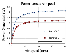
Considering the TWHRS, with 24 thermoelectric modules, one can predict the generation of 120W of power from 20 m/s, reaching 124W at maximum speed. Despite the large increase in speed the incremental effect on power increase is small, since the generation depends only on the temperature gradient that stabilizes after 20 m/s.
As a comparison, we cite the work developed by BMW researchers in 2009 who obtained an electrical power of 200W from a system of 24 Bi2Te3 thermoelectric modules installed in the engine of a BMW 535i at 130 km/h [37,42,43], showing that, respecting the particularities of each work, the results presented here are in the same order of magnitude and are therefore consistent with what is proposed.
Finally, the thermal to electrical energy conversion efficiency as a function of temperatures is presented in Fig. 11. It can be seen that the maximum efficiency occurs when Th≈ 230ºC and Tc=30ºC. For the temperature at the hot face of 300°C, the efficiency falls slightly below 6% for both Tc=50ºC, and Tc=30ºC, being 5.9% and 5.7%, respectively.

For the case study, with T(c,min)=32ºC, the efficiency would be 5.8%. Although this efficiency value is considered low in relation to combustion in thermoelectric plants (in the range of 35%) and internal combustion in automobiles (in the range of 30%), the value is quite considerable for a Bi2Te3 thermoelectric generator, whose maximum values reported in the literature can reach 8.45% [38,39].
The efficiency of any thermoelectric material whose figure of merit has a unit value is at most 20% of the Carnot efficiency, which in the best case scenario would reach the value of 20%, which is not the case for most of the materials used in practice today, whose figures of merit are below unity [40].
The maximum conversion efficiency is given as a function of ZT by Equation 1, where the higher the values of ZT, the higher the efficiency of the conversion of thermal energy into electrical energy by a given material [29].

From Eq. 1, one can see that higher efficiency values can be obtained with materials whose ZT values are greater than unity, such as rare earths, skuterudites, clathrates, and thermoelectric oxides [44].
The power generated can be used to supply the demand of the electric parts of the car dashboard, air conditioning, and can also help charge the battery.
Consider a hypothetical gasoline-powered car with a range of 10 km/L. Considering the calorific value of gasoline as 43000 kJ/kg [41] and its density as 0,745 kg/L [41], considering the combustion efficiency of the engine as 30% [39] and therefore the thermal losses as 60%. For each 1 L of fuel, the heat lost with the exhaust gases is of the order of 19221kJ. Considering that the thermoelectric generator is able to use 5.8% of all waste heat, the recovered heat is 1134 kJ, which in terms of overall efficiency of the car represents an increase of 3% or 10% of the current efficiency, quite a considerable value. The car would then have a range of 10.3 km/L.
In practice, however, a good deal of heat is lost before it reaches the muffler, through the pipe walls and exhaust system components. Considering the case where 50% of the heat lost from the flue gases is lost before it reaches the muffler, the increase in efficiency would be 1.5%.
A. Modeling Boundary Conditions
The TWHRS was analyzed on a steady state basis, however, to obtain the generated power one must perform a transient analysis, where the ambient air temperature and the temperature in the TWHRS vary temporally and cyclically. However, as a first approximation the steady state analysis provides a good estimate of the TWHRS operation.
Although it was considered, fixed temperatures at the TWHRS faces, it is known that, due to heat losses throughout the system, the temperature varies spatially between the first and the last TEG of each module. Due to the difficulty of modeling this variation, which in turn depends on the heat transfer of the hot gases inside, only fixed temperatures were considered, which nevertheless results in a good initial estimate.
The simplified outdoor airflow analysis uses only correlations to approximate the convective flow, however, being an embryonic project, it was satisfactory to obtain an analysis of the flow. In future work, the spatial variation of air temperature may be considered, as a result of the flow in the upstream hot parts.
Another consideration is the laminar analysis, which in practice is turbulent flow with recirculation zones. In the future, a Computational Fluid Dynamics (CFD) analysis can be used to improve the results and optimize accuracy.
5. Final considerations
The thermoelectric effect has been shown to be viable for the generation of electrical power in a multitude of applications as a non-polluting source, with no moving parts and low maintenance requirements. Requiring only a temperature gradient to generate electrical power for energy supply as a primary source or cogeneration, leading to increased efficiency of energy conversion systems.
The use of TEG's in automotive heat recovery systems is a promising technology with a tendency to develop in the coming years. As commercial barriers due to the high cost and the improved efficiency of thermoelectric materials are overcome.
The model of a thermoelectric generator was proposed to be coupled to the rear muffler of a car, whose average temperature is close to 300ºC. The geometry of the exhaust duct adopted is similar to that reported in the literature and was adapted for the thermoelectric generator incorporated in the muffler, taking into account the need to have flat faces for the best adaptation of commercial thermoelectric modules and to maintain a good surface area.
From the computational model, the generation obtained by TWRHS was evaluated, being estimated for a temperature gradient of ± 270ºC, the system would be able to generate a power of 120 W, with an efficiency of 5.8%. The effect on the overall performance of a gasoline-powered automobile could be an increase of up to 3% in overall efficiency, showing a great potential for utilization.
With the advance of the materials manufacturing technology and the reduction of the production costs, materials with even larger ZT can be economically accessible, making feasible the large scale implementation of TWHRS type systems, contributing to the increase of the combustion automobiles' efficiency and consequent reduction of the pollutant gases emission.
Finally, it is emphasized that TWHRS can be applied, with the proper adaptations, to any industrial steam and gas exhaust system to promote energy efficiency.

