


 English (pdf)
 Article in xml format
 Article references
 Send this article by e-mail
 Cited by SciELO
  Cited by Google
  Similars in
SciELO
Similars in
SciELO  Similars in Google
 Permalink
Introduction
X-Ray Photoelectron Spectroscopy - XPS is a powerful technique that can provide information about the chemical elements present on the surface of a sample. In this technique, the sample is irradiated with an X-ray beam with determinate energy. The photons can transfer their energy to the electrons present in the sample. If the transmitted energy is higher than the "binding energy", the electron is ejected from the sample with energy (Ek) equal to that expressed in Eq. (1):

The binding energy (Eb) can be defined as the necessary energy to eject a given electron from the sample. The term Ø represents the lost energy for an electron in the trek from the sample to the analyser. The information obtained by means of this technique comes from approximately the first 10 nm from the surface [1-3].
The binding energy of an electron principally depends on the atomic number of the element (Z), energy level (n), subshell (l), and spin-orbit coupling. The oxidation state and the chemical environment (specie formed) can cause a slight shift in the binding energy. In this sense, this technique can also provide information regarding the chemical species (oxidation states and compounds) present in the sample. Normally, the higher the oxidation states, the higher the binding energy shift (positive). Furthermore, the more electronegative character of the neighbouring bonded elements, the higher the binding energy shift (positive) [3-5].
XPS is widely used in many science fields related to materials and catalysis. This technique is a powerful tool to understand how the surface of a material is composed. In heterogeneous catalysis, the surface of the catalysis generally plays the principal role in the chemical reaction because the active sites are situated in this area, thus, it is important to know the surface chemical composition of a catalyst [6, 7]. For some catalyst materials, the surface composition can be very different from the bulk composition. This discrepancy may be due to the material nature, synthesis methods or contaminants.
In this work, a case of contamination with fluorine was studied employing XPS (and other analytic techniques). The catalysts studied were based on TiO2 supports which were treated with organic solvents as a part of the synthesis procedure. The organic solvent used was dehydrated using high temperature prior to the reaction employing mountings where Teflon tape and Teflon stirrers were part of the mountings, hence, these Teflon-based materials could become an important contamination source.
Materials and methods
Reagents
Benzene and Na2SO4 were purchased from Merck Millipore, Germany. TiO2 P25 was purchased from Degussa, Spain. Cetyltrimethylammonium bromide (CTAB) and HCl (37 wt%) were purchased from Acros. Ethanol (absolute RG for analysis), MoO2Cl2 and NaOH were obtained from Aldrich, United States.
Experimental
The samples Cat-1 to Cat-5 were synthetised according to the methodology set forth by Martínez et al. [8]. The synthesis procedure is not widely presented in this work due to the fact that this information does not have an important role in the aim of this work. An important step for the synthesis of these materials is the dehydration of the organic solvent (benzene) because the water present in the solvent can cause some not desired effects.
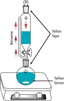
In the dehydration step, benzene is placed together with Na2SO4 into the glass system shown in Figure 1. The temperature is maintained at 180 °C. A magnetic Teflon stirrer is placed into the round flask. The glass connections are covered with commercial Teflon tape.
Characterisation by X-Ray Photoelectron Spectroscopy (XPS)
The contamination due to Teflon was studied by means of X-Ray Photoelectron Spectroscopy and Scanning Electron Microscopy / Energy Dispersive Spectroscopy (SEM-EDS). XPS experiments were carried out with a SPECS® XPS/ISS/UPS Surface Characterisation Platform. The samples were analysed using a monochromatic Al Kα X-ray source operated at 200 W/12 kV. The pressure in the analysis chamber was set at 10-10 mbar. The pass energy of the hemispherical analyser was set at 60 eV for the high-resolution spectra and 100 eV for the survey spectra. The samples were mounted on carbon conductive tape over the metallic sample holders. Surface charge compensation was controlled with a Flood Gun. The reference scale was calibrated by adjusting the adventitious carbon C-H to 284.8 eV. The Relative Sensitivity Factors (RSF) values employed in the quantification procedures were: C 1s (1.0), O 1s (2.77), F 1s (4.02) and Ti 2p (7.57), supplied by SPECS for the PHOIBOS analyser in magic angle geometry. Not all signals recorded were taken into account for quantification. The XPS spectra were analysed using CasaXPS software. All the signals were treated using static Shirley background and fitted using Gaussian-Lorentzian functions.
Characterisation by Scanning Electron Microscopy / Energy Dispersive X- Ray Spectroscopy (SEM - EDS)
Analysis by SEM- EDS was carried out in a ZEISS EVO50 scanning electron microscope, equipped with an energy dispersive (EDX) analyser, operated under the following analytical conditions: I probe 1 nA, EHT = 20.00 kV, beam current 100 μA, Signal A = SE1 and WD = 8.0 mm.
Results and discussion
A set of 5 catalysts synthetised using dehydrated benzene was analysed by XPS with the purpose of studying their chemical composition on the surface. Figure 2 shows the survey spectrums for each catalyst synthetised and for the TiO2 support before contact with dehydrated benzene. Ti 2p, O 1s, Mo 3d, Mo 3p, Si 2p, Si 2s, and C 1s signals are expected to be present in the catalysts due to the nature of the chemical composition of the materials analysed. C 1s was produced mainly by adventitious carbon.

According to Figure 2, these aforementioned signals were found in all samples analysed, however, Cat-1 to Cat-5 samples also showed a F 1s signal which was not found on the TiO2 support. Table 1 shows that F/ Ti ratios for the analysed samples were about 0.11 - 1.37, showing that F concentration on the surface of the analysed materials was relatively high.
Table 1 Surface chemical information of Cat-1 to Cat-5 catalysts

a Atomic ratio calculated using corrected areas
b Calculated using total F 1s signal and C 1s signal associated to CFx species. This value is an approximation.
According to the reagents used for the synthesis of each catalyst, none of the reagents contain a compound containing fluorine, therefore, the F 1s signal must be caused by a non-desired specie present in a contaminant. The binding energy of the main component present in the F 1s signal for every sample was about 689.5 e V. According to this binding energy value, the F 1s signal shown in each catalyst can be assigned to a CF2 specie [9, 10]. In addition to CF2 signals, CF and CF3 species were also observed in most of the analysed samples (see Figure 3). Table 1 shows the speciation for each component present in F 1s for all samples.
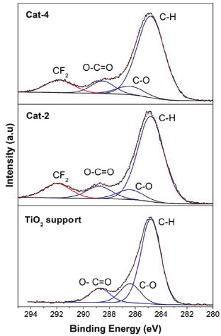
On the other hand, the C 1s signal is almost present in all samples analysed by XPS because this signal is also caused by adventitious carbon. Adventitious carbon is usually fitted using some representative species, they are: C-C (288.8 eV), C-O (286.4 eV) and O-C=O (288.5 eV) [11, 12]. Additional species of carbon could be caused by components present in the sample or by contaminant species. As mentioned previously, the binding energy for an electron in an atom depends on the chemical environment, so, if carbon atoms are linked to fluorine atoms in a specie, then there must be a C 1s signal with a binding energy value related to the CF2 specie.

Because of the higher value of electronegativity of fluorine atoms, the binding energy of the C 1s signal associated to the CF2 specie must be high, most likely higher than the binding energy found in C 1s of the O-C=O specie. According to Figure 4, species with binding energy associated to CF2 (~290.8 eV) species are also observed on the samples in samples Cat-2 and Cat-4, and therefore, contamination by Teflon on the surface of the synthetised samples is confirmed [9, 10, 13]. In addition, the F/C ratios found in the analysed samples were between 2.02 and 2.98. Although the expected value for the F/C ratio for Teflon is 2 [14], in this work, values for the F/C ratio were in general higher than the expected value.
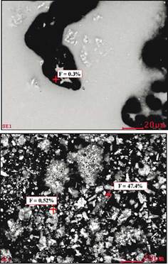
The sample Cat-2 was also analysed using SEM-EDS with the purpose of detecting fluorine. As shown in Figure 5, fluorine is also detected by SEM-EDS showing that F is not only located on the surface of the materials but it is also found in the bulk in relatively high concentrations.
These results show the difficulty of producing pollutant-free materials in various synthetic procedures. Although contamination by Teflon could go unnoticed for many bulk chemical techniques, XPS and other surface techniques provide specific information about the chemical composition of the surface and these analytical tools can provide valuable information to discover hard-detection contaminants deposited on the surface of synthetised materials. Teflon could be being released to the catalyst due to the effect of high temperature as well as the organic solvent used upon the Teflon tape and the magnetic stirrer. The friction between the magnetic stirrer and the glass of the flask can produce the releasing of Teflon to the organic solvent, and subsequently, it is fixed in the catalyst. Additionally, low quality Teflon tape could be partially fragmented by the action of heat and organic solvent vapour, and successively, come to the organic solvent to be finally fixed on the catalyst.
In this work, an investigation to determine which of the above probable sources are causing the contamination by Teflon on the catalysts was not undertaken. However, it is highly recommended that researchers who produce catalysts using similar conditions, verify that Teflon is not being released to the synthetised samples because it can be fixed on the surface of the materials and affect the catalytic properties of the desired materials.
Conclusions
XPS can be used as a valuable tool to study the chemical composition of the surface of synthetised materials. This technique can provide useful information regarding pollutant species present on the surface of the analysed samples and speciation procedures can be usually carried out with the purpose of identifying the contamination source. Special care must be taken when steps involving Teflon and organic solvents are carried out, because Teflon can be lixiviated from the tape or stirrer, and then become fixed on the synthetised materials.

