


 English (pdf)
 Article in xml format
 Article references
 Send this article by e-mail
 Cited by SciELO
  Cited by Google
  Similars in
SciELO
Similars in
SciELO  Similars in Google
 Permalink
1. INTRODUCCION
Sillenite crystals are cubic, photorefractive and electro-optical crystals, and are studied for their different applications, such as non-linear signals, optical interconnections and optical space. These material has electro-optical coupling, birefringence and optical activity. The photorefractive effect is the resposible the of refractive index change in the material for the space charge and the applied field. In this work we considered the polarization beams and non-moving transmission gratings. We calculated the diffraction efficiency fot the transverse configuration in Bragg regime. We considered the variation of fringe period. One crystals orientation is considered, with the grating vector KG is perpendicular to the crystallographic axis <001>
2. SET COUPLE WAVE EQUATION
The BTO is a material with electrooptic coupling and optical activity, the wave equation that governs light propagation is:

Where  is the total light field,
  is the magnitude of the optical wave vector,
  is the wavelength and
  is the free space permittivity.
For a birefringence medium with optical activity and electrooptic coupling, this constitutive relation can be expressed in the form:

Where  is the optical activity antisymemetric tensor,
  is the change in the permittivity tensor induced by the linear Pockels electro optic effect and
  is the symmetric optical permittivity tensor in the absence of optical activity and electro-optic coupling.
For the  orientation, the x axis is parallel to the [001] crystallographic face, as show in Fig. 1. The transformation matrix that converts from the crystallographic system to the light propagation system is:


For this orientation, the permittivity tensor exclusive of optical activity components, is:

where ,  is the index of refraction,
  is electrooptic coefficient and
  is the electric field inside of crystal. This field consists of two components:

Is the applied electric field and  is the space charge field, which depend of the diffusion and saturation fields. In the steady-state saturation limit, the space charge field is given by

In Eq. (6) E0 is the applied electric field of eq. (5), Ed is the diffusion field and Eq is an upper limit on the space charge field corresponding in a single trap model to saturation of available acceptor site (assuming monopolar charge transport in which electrons are the only mobile carriers). The diffusion field is defined by

where kB is Boltzmann's constant, T is the temperature and e is the electronic charge, the upper limit on the space charge field Eq is defined

where NA is the trap (acceptor) number density,  is the low-frequency dielectric constant and
  is the permittivity of free space.
The incident probe beam R is assumed to be well collimated with a small propagation angle  with respect to the z axis (Fig. 2). The signal beam will also be well collimated (assuming a single grating frequency) with a small propagation angle
  with respect to the z axis. Propagation angles obtained by rotating the propagation direction away from the z axis toward the +x direction (i.e., a clockwise rotation in Fig. 2) are defined to be negative. Thus, in Fig. 2, the probe beam R has a positive propagation angle while the diffracted signal beam S has a negative angle. The total light field of the two beams can be written as:


Figura 2 Top view of the grating readout process. Definition the propagation angles of the probe beam  and the diffracted signal beam
  .
.
The polarization states of the incident probe beam R and of the diffracted signal field S are two orthogonal linear polarization states which components is given by:

The set of coupled wave equations can be derived now that structure of the light field has been defined. The optical activity tensor can be added to the permittivity tensor, the constitutive relation for the  > orientation is:

Where is a parameter defined by  .
.
Using the slowly varying envelope approximation derives the coupled wave equations. The resulting coupled wave equations are:

where is the optical rotatory power and for convenience in eqs.(13-16) we define birefringence parameters Co and Csc by

For the transverse configuration we obtained the diffraction efficiency n, defined by

where  is the intensity of the diffraction light,
  the intensity of the incident light.
3. RESULT AND DISCUSSION
The theoretical analysis was realized using the Runge-Kutta method and its algorithm in the software Matlab.
In Fig. 3 we show the result for the dependence of the diffraction efficiency on the sample thickness for different applied field for a BTO grating using red light (632 nm) for reading. For this case,  , m =0.9 and F=179mm-1; the largest value of the diffraction efficiency occurs for an applied field of 10 kV/cm (see Table 1). We can see that the smallest of diffraction efficiency occurs for the smallest value of the applied field 1 kV/cm.

Figura 3 BTO crystal diffraction efficiency in terms of the crystal thicknesses using red read-out light and different applied electric fields Ea= 1kV/cm, 5kV/cm, 10kV/cm,  =47, m=0.9, F=179mm-1

In Fig. 4 we show the result for the dependence of the diffraction efficiency on the sample thickness for a BTO grating using red light (632 nm) for reading for different grating. For this case,  ; m = 0.9, m = 0.6, m = 0.3 and m = 0.1. The largest value of the diffraction efficiency occurs for modulation of 0.9.
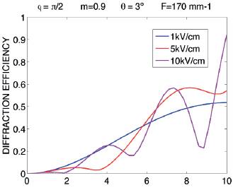
Figura 4 BTO crystal diffraction efficiency in terms of the crystal thicknesses using red read-out light and different modulation m = 0.9,m = 0.6, m = 0.3 and m = 0.1 for E0 =5kV/cm
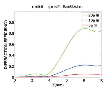
In Fig. 5 we show the result for the dependence of the diffraction efficiency on sample thickness for a BTO grating using red-out light (632 nm) for reading for different grating. For this case:  ; Eo=5 Kv/cm, m = 0.9;
  = 5µm, 10 (µm and 20(µm. In this case, the largest value of the diffraction efficiency occurs for a period of 20(µm. We can see that the smallest of diffraction efficiency occurs for the smallest value of period 5(µm, the largest value of the diffraction efficiency occurs for a period of 20µm.
4. CONCLUSION
We studied the diffraction efficiency in non-moving transmission gratings, in Bragg regime in transversal configuration in BTO crystal. A set of coupled-wave equations has been derived for transverse holographic orientation in crystal BTO of sillenite family. These equations allow an analysis to be made of the polarization properties of light diffraction including the effects of concomitant optical rotatory power. In the date analytic we used red light for the reading. We considered the birefringence, coupling electro-optic, optical activity, fringe period, different fields applied, different modulations and the polarization beams.
The results show that for a modulation of 0.9 the diffraction efficiency is greater that for a modulation of m=0.1. Also we can see that for the field applied of 1kv/cm correspond to the small diffraction efficiency while that for the field applied of 5kv/cm the diffraction efficiency is more stable. Too, for the fringe period of 5(µm the diffraction efficiency is smallest that for a period of 20 (µm. In conclusion, the thickness of sample in where occur the diffraction efficiency largest is in a crystal of 8mm.

