


 Inglés (pdf)
 Articulo en XML
 Referencias del artículo
 Enviar articulo por email
 Citado por SciELO
  Citado por Google
  Similares en
SciELO
Similares en
SciELO  Similares en Google
 Permalink
1 | INTRODUCTION
With the development of industry and technology, both the energy sector and information technologies are becoming very rapid advances. The sinus voltage sources used as energy sources are widely used to feed the load. And, these sources need to protect the sinus shape structures and not produce harmonics while feeding the load [1][2]. The sinus voltage source can include noises because the sinus source feeds nonlinear load or has environmental effects such as a high electromagnetic field. In this case, sinus welding performance on the load will decrease and energy losses will occur. Also, the deterioration of the sinus and similar signals used in modulation techniques affects the full formation of control signals at the circuit and information signals at the telecommunication. The deterioration of signals causes deterioration in the output values and an unwanted performance of the controlled load. In order to avoid all these unwanted situations, the loss of time and cost to create extra hardware occurs. Sliding mode control and fuzzy logic control for improving signals have been used frequently in some studies so far [3,4,5,6,7,8,9]. The artificial neural network (ANN) is used at the design of the weighting factors for a multilevel converter while artificial neural network provides a reliable technique for protection of multi-terminal high voltage direct current system systems [10,11]. Also, lighting estimation has been made with ANN in building and environment [12,13] while Adaptive Neuro-Fuzzy "ANFIS" has been used for Maximum Power Point Tracking Control for photovoltaic system in some studies [14,15,16,17] although modulation signal regulation has been provided by fuzzy logic control in a multilevel inverter [14], it is necessary to use a higher-level application such as ANFIS to correct a signal that contains too much noise. To demonstrate the correction effect of ANFIS in this study, after the electrical signals which are a pure reference signal and a noised signal can be expressed with a mathematical equation, adaptive fuzzy logic is to be applied to correct on a distorted electrical sinusoidal.
ANFIS is referred to in the literature by adaptive neural fuzzy inference system, Adaptive Neural Fuzzy Inference System or Adaptive Network-Based Fuzzy Logic Inference System. ANFIS is an adaptive network in which the topology of artificial neural networks can be used together with the principles of fuzzy logic. This method has the features of fuzzy logic and artificial neural network methods and eliminates some disadvantages when these two methods are used together according to used alone. It allows optimizing the values of the rule base and membership function to model fuzzy logic of known systems with input and output values. In ANFIS, it is provided to optimize the rule base and membership function values for modeling the systems with certain input and output values using fuzzy logic. In the application stage, firstly hypothetical reference signal equation x(t) is determined and clean signal views are obtained. The interference signals m2 appearing in the measuring signal is considered to be formed with an unknown nonlinear mathematical equation. After that, necessary noised signal equations m(t) are formed by adapting the noise signal m 2(t) to the hypothetical reference signal. The measuring signal m is calculated from the original information signal x and the interference m 2(t). The only signals are the signal with noise m1 and the measuring signal m are known. m is the sum of x(t) and m 2(t). The aim is to recover the polluted information signal x(t). So, after general signal properties are determined, ANFIS finds the nonlinear correlation between m 1(t) and m 2(t). Although m 2(t) is not directly known, m is considered as the contaminated model of m 2(t) for practice at the ANFIS. Thus x(t) is used as the noise of this kind of nonlinear. ANFIS with 2-inputs is employed for practice. Three triangular membership functions are employed to inputs of ANFIS. So, the total number of fuzzy rules is 9 for learning. Also, the step size is set to 0.01. All the training information is observed with receiving in command window of the MATLAB.
The results obtained show that the distorted signal approaches the clean reference signal with ANFIS. At the end of the first ANFIS study, the distortion value of the distorted signal is reduced from 18.11% to 4.32%. At the end of the second ANFIS study, the distortion value of the distorted signal is reduced from 18.11% to 1.21%. This value is much more ideal for power electronics applications and energy quality improvement applications and other signal processing and generation applications in [18,19]. So, ANFIS performs very good work. These results demonstrate that ANFIS can be used effectively on electrical signals, which means that it can be used as an effective option in preventing unnecessary hardware additions, preventing energy losses and reducing information losses.
2 | SIGNAL GENERATION AND SIGNAL CORRECTION
2.1 | Hypothetical Information Signal and Noise Signal
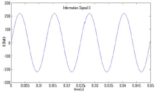
The x(t) described in volts (V) units is shown inf Fig. 1 is a hypothetical sinusoidal information signal sampled at 80Hz. This signal has a phase angle of 0o and can be mathematically given in Eq. 9 where ω is the angular frequency
If the signals of a three-phase network are to be considered, the other two signal with phase differences be written as in Eq. (2) and Eq. (3) given by
And
The noise forming on the single signal in the first equation of these three signals is reduced by using ANFIS. The information signal in Fig. 1 is clean and at a desired level for the system. However, the information signal x(t) must be measured with an interference signal m 2(t) which can form from another noise source m 1 from an unknown nonlinear process. The noise source signal m 1 is shown in Fig. 2. The interference signals m 2(t) appearing at the measured signal can assume to be formed from an unknown nonlinear mathematical expression as in Eq. (4)

where k is an iterator. Fig. 3 shows the source with noise m i and interference m2 together. Noise m2 is related to mi because of the highly nonlinear process demonstrated previously; it is difficult to see if these signals are related in any way.

The measuring signal m is found by summing of the reference data signal x and the parasite m 2. However, m 2 is unknown. The only, the signal with noise m 1 and the measuring signal m are known. The measuring signal m is expressed mathematically as in Eq. (5) while Fig. 4-a shows that m is a noised sinusoidal signal. This signal is given by
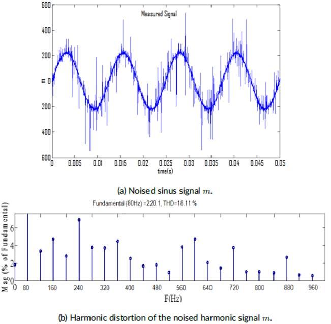
Fig. 4-b shows the harmonic distortion of the signal on which the noise is affected. The clean reference source signal in Fig. 1 contains a lot of noise signal as it is shown in Fig. 4. The noise on this signal greatly distorts the sinusoidal structure of the reference signal. Therefore, the harmonic distortion of this signal is 18.11%. This signal is not ideal for use in power electronics applications and the generation of signals used to carry information in communications and is therefore not preferred. Using this signal adaptive neural fuzzy logic method, the noise value of this signal will be reduced.
ANFIS is referred in the literature by Adaptive Neural Fuzzy Inference System or Adaptive Network Based Fuzzy Logic Inference System. ANFIS is an adaptive network in which the topology of artificial neural networks can be used together with the principles of fuzzy logic. This method has the features of fuzzy logic and artificial neural network methods and eliminates some disadvantages when these two methods are used together according to used alone.

FIG. 8. Estimated m 2.
It allows optimizing the values of the rule base and membership function to model fuzzy logic of known systems with input and output values. In ANFIS, it is provided to optimize the rule base and membership function values for modeling the systems with certain input and output values using fuzzy logic. The optimization process is done using the learning methods of the Artificial Neural Network. In this way, fuzzy systems, which normally do not have the ability to learn, are provided with the ability to learn the data sets to model.
ANFIS uses the back-propagation method or the combination of the back-propagation method and the least squares estimation method as the learning method [20]. ANFIS architecture consists of 5 layers. Each layer has neurons as many as the number of fuzzy logic rules. In this architecture, each layer performs a different function [21]. In Fig. 5 (a), the Sugeno method of the fuzzy logic system with 2-input and 2-rule is modeled [19]; Inference structure and the equivalent ANFIS architecture of this model are given in Fig. 5-b where p and q are the coefficients of the input terms constituting the function, r is the constant term of the function and w is the weight determined by the method.

In the fuzzy logic approach, the result part of a rule is a linguistic expression taken with expert opinion. However, this linguistic information can be expressed as the linear sum of the entries by the Sugeno inference method as follows
If
And
If
where x i and y i are input values, f 1 and f 2 scalar functions, q 1 and q 2 are coefficients, and r 1 and r 2 are constants. The final output is the average of the weights of each rule as in Eq. (8)
Noise reduction of a sinusoidal signal including noise is performed in accordance with the described rules. So, the determination of the nonlinear relationship between m 1 and m2 are found by the function ANFIS. Even when m2 is not known directly, m can be considered as a contaminated version of m 2 for practice.
Thus, x is determined as noise in this type of nonlinear fitting. For ANFIS, three mf consisting of triangles is used for both input values that are m and m 1. ANFIS in Fig. 6 is created in toolbox of Matlab for estimation of m 2. ANFIS in Fig. 7 is created in toolbox of Matlab for estimation of x. Input m, membership functions mf11(m), mf12(m) and mf13 (m), 2nd input m 1 and membership functions are mf21(m 1), mf22(m 1) and mf23(m 1). The outputs of the membership functions are calculated as follows
if m = mf11(m) ˄ m 1 = mf21(m 1) then y 1 = f1(z, m, m 1)
if m = mf11(m) ˄ m 1 = mf22(m 1) then y1 = f2(z, m, m 1)
if m = mf11(m) ˄ m 1 = mf23(m 1) then y1 = f3(z, m, m 1)
if m = mf12(m) ˄ m 1 = mf21(m1) then y1 = f4(z, m, m 1)
if m = mf12(m) ˄ m 1 = mf22(m1) then y1 = f5(z, m, m 1)
if m = mf12(m) ˄ m 1 = mf23(m1) then y1 = f6(z, m, m 1)
if m = mf13(m) ˄ m 1 = mf21(m1) then y1 = f7(z, m, m 1)
if m = mf13(m) ˄ m 1 = mf22(m1) then y1 = f8(z, m, m 1)
if m = mf13(m) ˄ m 1 = mf23(m1) then y1 = f9(z, m, m 1)


ANFIS created in toolbox of Matlab for estimation of x. Input m, membership functions mf11(m); mf12(m) and mf13(m), 2nd input m 1 and membership functions are mf21(m 1); mf22(m 1) and mf23(m1). The outputs of the membership functions are calculated as below.
In the second stage, the relationships between the membership function outputs are formed and the output values of these relations are calculated. Relations between membership functions are achieved by matching each membership function at m in input 1 and each membership function at m1 in input 2. Since there are three membership functions for the first input and three membership functions for the second input, a total of 9 correlations will be obtained as follows
Correlation 1: C 1(m, m 1) = mf11(m)mf21(m 1)
Correlation 2: C 2(m, m 1) = mf11(m)mf22(m 1)
Correlation 3: C 3(m, m 1) = mf11(m)mf23(m 1)
Correlation 4: C 4(m, m 1) = mf12(m)mf21(m 1)
Correlation 5: C 5(m, m 1) = mf12(m)mf22(m 1)
Correlation 6: C 6(m, m 1) = mf12(m)mf23(m 1)
Correlation 7: C 7(m, m 1) = mf13(m)mf21(m1)
Correlation 8: C 8(m, m 1) = mf13(m)mf23(m 1)
Correlation 9: C 9(m, m 1) = mf13(m)mf23(m 1)
In the third stage, the relations between membership functions are subjected to a process called normalization. The normalized value of the relationship is obtained by dividing the relationship output value by the sum of the output values of all relationships. The sum of all relationships C T is calculated as follows
The normal values of the relationships are calculated as follows
jth-Normal:
In step 4, the output functions {F i}i=1,2 ,9 of the system are calculated as in Eq. (11). Z are the coefficients of the terms in the series and iЄ [1,9] ⊂ℕ. Those functions are given by
In the stage-5, the normalization outputs and the system output functions are multiplied and the multiplication results are summed and the system output value y is obtained as in Eq. (12). C T is calculated as in Equation 20 this is
and the value of y is computed as follows
The information of ANFIS is presented in Table 1. ANFIS training is completed with epoch 10 (see Table 2). After ANFIS training completed; estimated m 2 is as in Fig. 8 while estimated x is in Fig. 9. The distortion values of the corrected signal as a result of the first ANFIS study applied to the noise affected the harmonic signal are shown in Fig. 9-b.
TABLE 1 ANFIS Information.
| Number of nodes | 35 |
| Number of linear parameters | 27 |
| Number of nonlinear parameters | 18 |
| Total number of parameters | 45 |
| Number of training data pairs | 5001 |
| Number of checking data pairs | 0 |
| Number of fuzzy rules | 9 |
TABLE 2 ANFIS training.
| Epoch | Step size | |
| 1 | 155.305 | |
| 2 | 155.305 | |
| 3 | 155.305 | |
| 4 | 155.305 | |
| 5 | 155.305 | |
| Step size increases to 0.011000 after epoch 5 | ||
| 6 | 155.305 | |
| 7 | 155.305 | |
| 8 | 155.304 | |
| 9 | 155.304 | |
| Step size increases to 0.012100 after epoch 9. | ||
| 10 | 155.304 | |


At the end of the first ANFIS study, the distortion value of the distorted signal is reduced from 18.11% to 4.32%. This value is ideal for power electronics applications and energy quality improvement applications and other signal processing and generation applications. By making new arrangements on relationships and Ns, a new estimate can be created for further correction of the signal as in Figure 10.

The normal values of the relationships at the Fig. 10 are calculated as follows
Normal 1: N 1 = mf11(m)mf23(m 1)/C T = C 3/C T
Normal 2: N 2 = mf21(m)mf21(m 1)/C T = C 4/C T
Normal 3: N 3 = mf11(m)mf21(m 1)/C T = C 1/C T
Normal 4: N 4 = mf11(m)mf22(m 1)/C T = C 2/C T
Normal 5: N 5 = mf13(m)mf22(m 1)/C T = C 8/C T
Normal 6: N 6 = mf13(m)mf23(m 1)/C T = C 9/C T
Normal 7: N 7 = mf12(m)mf22(m 1)/C T = C 5/C T
Normal 8: N 8 = mf12(m)mf23(m 1)/C T = C 6/C T
Normal 9: N 9 = mf13(m)mf21(m 1)/C T = C 7/C T
and y is evaluated by using Eq. (12). The signal obtained after further modifications to the ANFIS is shown in Fig. 11-a. The distortion values of the corrected signal as a result of the second ANFIS study applied to the noise affected harmonic signal are shown in Fig. 11-b.
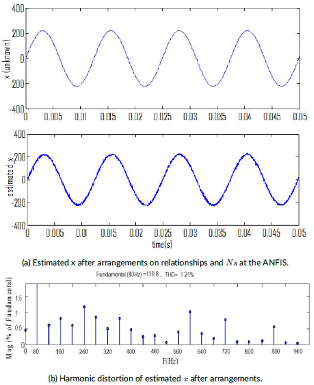
At the end of the second ANFIS study, the distortion value of the distorted signal is reduced from 18.11% to 1 .21%. This value is much more ideal for power electronics applications and energy quality improvement applications and other signal processing and generation applications.
The estimation of m 2 is successfully made by the network of 5-layer adaptive neural fuzzy logic in Fig. 6. The estimated signal x is obtained from signal m with noise pollution as in Fig. 9. The distorted sinus signal is shown in Fig. 9, which is very close to the hypothetical clear signal after it corrected. In the second experiment, the signal is further corrected after C and N are arranged for new coupling. Then, the noised signal approaches the reference signal according to the first experiment. Therefore, ANFIS performs good work on the electrical signal. These results show that it can be used both in the correction of the distortions to occur in the loads fed by the sinus voltage source, or in the correction of the signals to be used in modulation techniques for control or information transfer purposes. Therefore, extra equipment will not be necessary for the correction of the signals. Extra energy losses in energy transmission will be avoided. By modifying the noise of the signals used in modulation, an effective switching control is made. Additionally, the loss of information will be prevented by eliminating the noise in the modulation signals in data transportation of communication.
3 | CONCLUSIONS
The correction of the distorted electrical signal with an adaptive fuzzy logic (ANFIS) due to noise forming in electrical signals was discussed. Therefore, after considering the structure of the clear reference signal equation, a noise that occurred in the sinus structure was included in the clear reference signal structure. The measured information signal with an interference signal that was formed from a separate noise source with a nonlinear process that was a certain unknown. After an interference signal was generated, the measured signal was given with the original information signal, and the interference summing. In the correction stage of the signals, the adaptive fuzzy logic system in the Matlab toolbox, the source noise signal, and the measured signal values were entered. Then, the experiment is performed via a 3-triangular membership function. According to our results the distorted signal after the correction operations was very close to the reference signal. Therefore, ANFIS was affected on a noised electrical signal.

