


 Inglés (pdf)
 Articulo en XML
 Referencias del artículo
 Enviar articulo por email
 Citado por SciELO
  Citado por Google
  Similares en
SciELO
Similares en
SciELO  Similares en Google
 Permalink
1. Introduction
In the creation and development of machines for the execution of tasks with high industrial demands, materials testing, and technological applications in other areas of engineering, there is a problem, and that is how to develop machines exclusively for the characterization of emerging nanostructured materials capable of fulfilling all the tasks required, the design of machines is in a context of continuous evelopment that seeks to reduce errors in planning, modeling, and manufacturing. Based on the theory of the coining principle and the machines currently used to carry out this process, we proceed with the approach and obtaining of the nominal force [1,2], the definition of power transmission systems[3], and the selection and design of the structural frame. The following operating principles were taken into account to carry out the machine design: [1]Modern coin minting machine, [2]eccentric mechanical press, and [3] die; the combination of the first two items allows establishing the required loading criteria, while the third item helps to determine the tool alignment and stroke requirements. Today, computer design programs allow machines to be evaluated and validated from the design phase as many times as necessary before moving on to the manufacturing phase. The simulation of the machine’s work is a phase of the process that makes it possible to substantially improve performance by facilitating the detection of any anomaly not foreseen in the design phase, reducing the amount of testing in real life, and also making it possible to analyze and evaluate the safety factor by reducing the probability of generating failure due to fatigue or overload[4].
Nanostructured coatings are those thin films implemented to coat the surfaces of tools used in cutting, punching, or friction work to provide more excellent wear resistance and surface hardness. When the coating is applied to the tool, it forms a metallurgical bond that does not delaminate, generates chips, or create a peel; in fact, the coating is deposited slightly on the tool’s surface layer [5]. The adhesion is superior to veneering and other coating processes where mechanical bonding occurs [6]. The excellent results of the behavior and the contribution in the surface resistance of nanostructured films’ physical properties in the most demanding works [7] are an impulse to stimulate the research and development of a great variety of nanostructured unique properties materials [8]. Based on these findings, a concept of high hardness coatings has been developed, the films with hardness H<40 GPa and H>40 GPa are currently described as hard and super hard, respectively [9]. One of the materials currently being implemented and under which the FEA analysis is based in the present study is titanium nitride (TiN), which has a hardness range of 2500 HV to 3000 HV (24 GPa to 30 GPa) [6]. In previous studies, the TiN coating shows a low coefficient of friction, and in pin-on-disk tests, it shows resistance to excessive wear at ambient temperature and high temperatures, up to 500 °C [7]. The microstructure and the coating film thickness strongly influence the nanostructured coating failure mechanism [10]. The study relevance of the nanostructured coating in the coining process is that this new generation of materials provides superior mechanical properties that increase the tool’s life and provides reliability in the coining process.
The objective of this study, then, is to propose the design and CAD-CAE simulation of a mechanical test press that subjects to working load conditions the coining and punching tools containing nanostructured coatings. The FEA simulation for the coining tool is carried out with the mechanical properties of M2 high-speed steel.
2. Design methodology
A machine is needed to impact test coining tools; these tools have nanostructured coatings that improve the work surface’s hardness and provide more remarkable performance. The design of the testing machine is based on the approach of essential parameters, which are (1) the working area of the punch, (2) coining depth, and (3) yield strength of the material to be deformed. From the basic parameters we proceeded to obtain the nominal force under which the machine will work; this is the basis for the selection of the drive system (see phase 1 in Figure 1]. The power transmission systems proposed to generate and transmit the nominal force of the test tool are the transmission by pulleys, gears, and crank mechanism.
Previous to the CAD-CAE design, the static and dynamic analysis of the test press’s mechanisms is carried out, the parameters are set out according to the information provided in previous research, design books, and studies. The movement profile is defined based on the crank mechanism’s interaction and behavior relationship and the ram stroke. The maximum nominal force in the structure is generated at the travel limits at 0.5 mm before contact with the test sheet. Finally, a rendering of the CAD modeling with its respective final assembly is presented. The table of technical specifications is presented in Table 1.

3. Crankshaft system
The crankshaft is part of the crank mechanism and is the element that transmits the torque it receives from the gear transmission system to the connecting rod [4]; this system is the center of analysis in this document. See Figure 2. Figure 3 shows the crank and ram-die systems; finally, the crank transfers the nominal force through the ram to the coining tool that fits into the punch holder.

The crankshaft mechanism is the last and most crucial transmission system in the mechanical test press because it generates the maximum forces and represents the forces behavior to which the machine is subjected. The dynamic analysis of the crank mechanism and ram transmission system is represented below.
3.1 Crankshaft pin
The transmitted torque from the gear transmission system is 1056 Nm. This is converted into various forces that are distributed on the crankshaft pin; see Figure 4. The crankshaft pin is responsible for transmitting the nominal force to the connecting rod. This section of the crankshaft is the most critical because, at the same time, it must support the reaction forces generated by the impact of each tool. As a requirement for the crankshaft, a radius of eccentricity r=50 mm was assigned, the ram stroke is H=100 mm, the connecting rod was assigned a length l=500 mm.


Crankshaft pin forces

The tangential force Ft is obtained from the torque transmitted from the gear system. See Equation (1), then the forces generated in the crankshaft pin are obtained, which in turn will be transmitted to the connecting rod FCR [11].
See Equation (2).


Where Mc is torque, r is the radius of eccentricity, and FCR is the connecting rod’s transmitted force.
From the force FCR and with the angles α and β, the radial force was obtained. Reaction forces are generated which act on the crankshaft pin[11]. The maximum reaction force was the reference for obtaining the crankshaft pin diameter. The reaction force is the radial force supported by the crankshaft pin bearing [11,12].
Crankshaft pin stroke
The crankshaft pin contemplates the stroke from TDC to BDC. Equation (3) obtained[12].

Where TDC is top dead center, and BDC is bottom dead center. Angles α and β were also used to solve the equation of stroke variation of the ram H r . Data from 180° (TDC) to 0°(BDC) were posed, see Figure 5(a), to obtain more specific data of the ram’s stroke concerning the variation of the angle α. The following figure shows the change of angle α and the ram’s stroke.
Between the angles > 15° and < 165° the ram has the most remarkable changes in position, in the vicinity of the TDC and BDC, the crankshaft position angle changes slightly, causing the force of the connecting rod to concentrate and increase rapidly. As evidenced in Figure 5(b), the connecting rod’s maximum force is at the ends of the ram’s troke.
Ram

The ram is responsible for transmitting the linear force converted by the connecting rod to the coining tool, see Equation (4). The upper die system is coupled to this component, and together with the die guides it is responsible for providing the maximum alignment and stroke of the tool, see Figure 6.


Where FR is the force of the ram that is transmitted to the coined tool.
Normal force
The normal force is applied mainly on the guides of the ram’s stroke; this force generates vibrations in the machine. Therefore, the design that was made for the guides reduces the generated vibrations to the maximum, see Equation (5).

Where Fn is normal force.
Table 2 shows the behavior of the normal force produced in the ram’s guides, according to the force transmitted by the connecting rod with respect to the angle β.

The magnitude of the normal force acting on the ram’s guides decreases slightly during the crankshaft’s stroke from the TDC to the BDC, with the most significant force occurring at an angle α equal 179°.
4. Structural frame
The frame on which the force calculations and FEA analysis were performed is of type C. The dimensions of this type of structural configuration for high capacity work can be smaller than other types of structures, such as type O [12]; the simple design makes it possible to modify the dimensions quickly according to the design considerations. The permissible forces FM to which the press tructure will be subjected are represented, this according to the nominal force F, see Equation (6), crankshaft position, angle, and ram stroke [12].

Where Hmax is maximum ram stroke from TDC to TDC and h is stroke position In theory, for angles α < 30° and α > 150° the coining force tends to infinity, at an angle of 90°(half stroke) the force decreases by half [12], increasing rapidly in the vicinity of the stroke points 0 mm and 100 mm. Figure 7(a) shows the behavior of the forces according to the variation of the ram’s stroke. The relationship between the angles α (crankshaft pin position) and β (connecting rod position) is also shown; see Figure 7(b).

The maximum angle β is given at an angle α of 90° (half stroke), this is where the minimum nominal force is presented for the ram stroke.
4.1 Structural frame plates
The structural frame plates are responsible for supporting all the components and mechanical transmission systems of the press. The final sheet thickness (t) can be modified according to the different simulations, loading conditions, and finally, the mechanical elements position configuration. First, the allowable stress σp is required; see Equation (7); since it is a C-frame, the thickness applies to the two plates that give shape to the structural frame. The plate thickness calculation is only a primary design condition for the subsequent analysis of stresses and deformations through FEA analysis, see Equation (8)[13].


Where SF is a safety factor

Where F is nominal force, l in is the distance from impact center to press frame, and l w is the width of the plate.
5. Structural design
The overall dimensions and resistance and the components and the structural frame are determined theoretically determined previous to CAD model and the assembly generation. The calculations are performed under static parameters and with point reaction forces. The critical components of the press that will be subject to the safety factor analysis are: flywheel, primary shaft, and crankshaft. The analysis is given corresponding to the assemblies that are subjected to fundamental reaction forces. The assemblies analyzed are geared transmission system, connecting rod, ram, and structural frame. As the machine is focused on high nominal capacity, the safety factor calculating the dimensions and cross-sections of most critical components is SF=4. There are cases in which the safety factor can be higher, and it is since, in the theoretical calculations, the safety factor was applied in specific sections of the components; therefore, the final results of the analysis change since the FEA analysis is performed to the whole component or assembly. For non-critical components, a safety factor of SF ≥ 2 is projected; materials are selected according to manufacturers’ recommendations and facility of acquisition.
6. FEA analysis
The results of the analysis in all components are focused on three sections:
Maximum stress based on the theory of von Mises - Hencky.
Resulting displacements URES.
Safety factor SF.
A convergence analysis is performed to apply fine mesh with an overall element size of 2.46 mm; this is the maximum fine-mesh density allowed by the design program implemented for the analysis; therefore, it is the implemented mesh density for all analyzed components and assemblies. In this section, the safety factors were obtained; the Equation 9 poses a general approach to the classical design mode [14], also under which FEA analysis programs are governed to obtain results.

Where Sy is yield strength, and σmax is the maximum von Mises stress generated in the analysis.
The safety factor scale used in this section for all components and assemblies of the testing machine starts at one and ends at ten.
6.1 Flywheel
A flywheel; see Figure 9(a), is an energy storage device that absorbs and stores kinetic energy when it spins rapidly but returns the energy to the system when needed, reducing its rotation speed [15]. The analysis of the flywheel is done by applying a geometric restriction (green arrows) on the outer ring that has a thickness of 162 mm; see Figure 9(b). For some maximum stress, a torque of 237.36 Nm is applied in the bushing that supports it; see purple arrows. The torque is obtained according to the calculation of transmission ratio and drive system. Table 3 presents the details of the mesh and results obtained in the FEA analysis.
Figure 10 shows the results of maximum stress, displacements, and safety factor.
Cast iron was the material assigned for the analysis since it presents greater feasibility for manufacturing components that require high tensile strength; the advantage of this type of material are high rigidity, machinability, and excellent vibration damping [16].


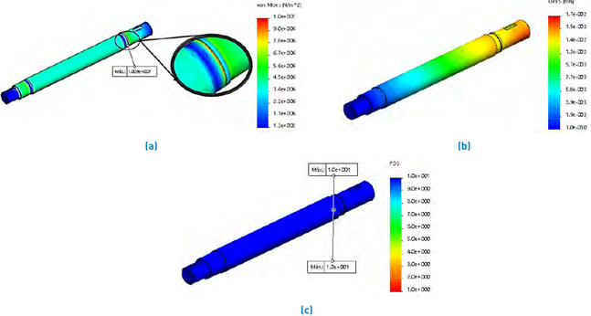
Figure 12 Primary shaft: (a) von Mises stress analysis, (b) resulting displacement, (c) safety factor.

As shown in Figure 10(a), the maximum stress is located near the point of contact between the bushing and the flywheel; the maximum displacement is concentrated in the vicinity of the contact between the hub and the flywheel; see Figure 10(b), the final safety factor shows that the flywheel distributes the stresses evenly; see Figure 10(c), the bushing should be considered the component that concentrates most of the stress in the analysis; therefore, further studies and analysis of the behavior of this component can be performed. Additionally, a low cycle fatigue system may require a strain-based fatigue failure analysis rather than a stress-based one, especially if there is a possibility of transient overloads that will cause the stresses produced to exceed the yield strength ultimate[15].
6.2 Primary shaft
The primary shaft is responsible for transmitting the torque received from the flywheel to the pinion; this component is part of the gear transmission system; see Figure 11(a). The material implemented for the shaft is 4140 OQT 1000 steel; this provides excellent corrosion resistance and strength up to about 600°C. These features include high strength and good machinability that can easily be heat treated for greater hardness[16,17]. The analysis is carried out by applying the torsional moment or torque in the section where the flywheel is mounted (most extended cantilever section); see Figure 11(b), the torsional moment is the same applied in the flywheel analysis. Table 4 presents the details of the mesh and results obtained in the FEA analysis. Figure 12 shows the results of maximum stress, displacements and safety factor.

The ultimate yield strength of the material is 1050 MPa, the maximum stress is 10.09 MPa, see Figure 12(a), which ensures an infinite working life of the shaft. The primary diameter calculation for rotating shafts was supplemented with critical speeds. Bending displacements at the shaft ends were calculated with resulting forces and masses. The calculations were supplemented with the torque deformation analysis; the resulting slip is 0.0174 mm; see Figure 12(b). The safety factor is higher than four because the sections went through after a critical speed analysis; a modification in the final diameter was made, this modification is made considering the permissible deflections for shafts and beams[3].
6.3 Gear transmission
The gear transmission system is the most critical, together with the connecting rod and crank system. Because the gear teeth are in charge of transmitting the nominal force, they must have the highest reliability [15]; see Figure 13(a). The analysis was carried out with the torque T=237.36 Nm on the pinion and a transmission ratio of 4.4:1, see purple arrows; the gear was analyzed as a fixed geometry part, see green arrows in Figure 13(b).
Table 5 presents the details of the mesh and results obtained in the FEA analysis. Figure 14 shows the results of maximum stress, displacements and safety factor.

The yield strength of the material is 1090 MPa, and the maximum stress is 23.28 MPa (see Figure 14(a)); the gear system must have high reliability because the transmission of the nominal machine force depends on the bending strength of the teeth [15]. The maximum stress results indicate a high degree of safety of the gear teeth. The safety factors of the surface and the bending of the teeth are also calculated, giving a bending safety factor for the pinion teeth of SF=2.3 and for the gear teeth of SF=4. The safety factor for surface failure is SF=1.3. The transmission system is relatively safe, and it should have a 99% probability of lasting 360 × 106 cycles, approximately 6.8 years before the teeth are manufactured. As shown in Figure 14(b), the maximum displacements are located in the pinion teeth; as the power transmitting component is minor, it is subject to more stress and deformation. The resulting displacement is 0.0252 mm, which is optimal for the whole transmission system.
6.4 Crankshaft
The crankshaft is the component subjected to the most significant stress in the mechanical test press because it must resist the reaction force transmitted to the crankshaft pin and the radial and tangential forces transmitted from the gear system. The crankshaft’s critical point to be tested was the crankshaft pin, which is in charge of transmitting the force and resisting the reaction force; the same as it has to support the mass of the connecting rod and the ram-die system; see Figure 15(a). The analysis is performed by applying a vertical reaction force in the direction of the crankshaft pin with a magnitude of 1344.87 kN, and this is the only force above the nominal force that was applied for this component; this force was applied because in the results of crankshaft pin forces; see Figure 5(b). It is the maximum force within the stroke of the connecting rod to which the crankshaft is subjected. The radial force from the gearing in the direction of the shaft was also applied; see Figure 15(b). Table 6 presents the details of the mesh and results obtained in the FEA analysis.

As indicated at the beginning of the section, the safety factor results may change according to the analysis mode. For the calculation of diameter sections, where the bearings and connecting rod are assembled (the place where the reaction force is applied), a safety factor of four was applied. Now, for the connection of these diameters, some connections with specific dimensions were designed. As these connections do not have a specific calculation, the minimum safety factor is presented in that region; see Figure 16(c). The safety factor of four remains valid and provides reliability in the sections where the components are assembled and in the connections with the arms that support them.
The yield strength of the material is 1050 MPa with resultant maximum stress of 396 MPa, see Figure 16(a).

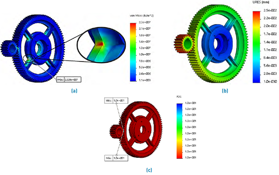
Figure 14 Gear Transmission System: (a) von Mises stress analysis, (b) resulting displacement, (c) safety factor.


When calculating the crankshaft pin diameter, an SF=4 was applied for allowable stress of 262.5 Mpa; according to the FEA analysis, the crankshaft section diameters maintain a safety factor ≥ 4, and the overall component complies by staying below half the yield strength. A component that is subjected to load reactions must provide the highest reliability to the system. The resulting displacement is 0.179 mm, see Figure 16(b); it should be noted that the force applied in this section is not the main force that must be supported; this is the force that is at an angle α of 179°. The real nominal force of reaction that must be supported is 800 kN, which means that the resulting displacement decreases approximately 41%, leaving a resulting displacement of 0.071 mm which is acceptable within the recommended deflection [3].
6.5 Connecting rod
The connecting rod was designed iteratively; the only input value used was the length of l=500 mm. The materials assigned were as follows: For the body of the connecting rod, superior component, and spherical plain bearing, the material assigned was SAE 4140 OQT 1000 steel, for the coupling between the spherical plain bearing and the body of the connecting rod, SAE 1020 steel, finally for the bearing, a laminated bronze; see Figure 17(a). The reaction force was applied in the ball-joint in a vertical sense, and the restriction of fixed geometry was applied in the bearing; see Figure 17(b). Table 7 presents the details of the mesh and results obtained in the FEA analysis. Figure 18 shows the results of maximum stress, displacements, and safety factor.

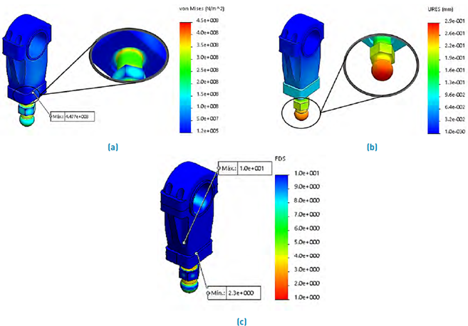
Figure 18 Connecting rod: (a) von Mises stress analysis, (b) resulting displacement, (c) safety factor.


The ultimate yield strength of the material is 1050 MPa with a maximum stress result of 447 Mpa; see Figure 18(a); the connecting rod meets by staying below half of the yield strength. The resulting displacement is 0.288 mm; see Figure 18(b); this is an acceptable deformation considering that the ball joint is the first component that transmits the reaction force, which presents a high degree of reliability for the work. In an extreme case where the component presents overload or fatigue fracture, its manufacture is not complex due to its simple design. With a safety factor of 2.34 the assembly meets the requirements set out at the beginning.
6.6 Ram-die
In the ram-die; see Figure 19(a), the reaction force was applied at the point of contact of the coining tool with the backing plate, and the restriction was applied where the connecting rod is assembled; see Figure 19(b). The die system was modified so that there was free space for the test sheet displacement system; this was done to accommodate the mechanical test press’s design. The ram was assigned the steel SAE 1045 cold drawn; for the plate, the steel SAE 4140 OQT 1000. The plate is the first component to receive the reaction force transmitted by the punch and where the most significant displacement occurs, see Figure 20(a), 20(b); therefore, it must present the highest resistance, and this is achieved with a material of high mechanical performance [17,18]. The ram-die system and the connecting rod were designed iteratively, respecting the manufacturers’ dimensions for the backing plate [19]. Table 8 presents the details of the mesh and results obtained in the FEA analysis.

Only for this analysis a safety factor < 2 was obtained. It is clarified that the point of contact of the water hammer with the plate is where the minimum safety factor is generated, as the ram is a rigid component, it can distribute the reaction force better; the shank that holds these two components together provides more excellent resistance as it is made of the same material as the backing plate. The yield strength of the plate material is 1050 MPa with a maximum stress result of 457 Mpa, see Figure 20(a). The system complies by staying below half the yield strength in the case of the plate, for the design of the ram was considered to be a rigid component, as it provides more excellent safety factor.
6.7 Structure
Initially, a design consisting of two sections was proposed, an upper section that would support the entire drive system and a lower section that would support the lower die system and the mechanism for moving the test sheet. According to the analysis results, it was decided to design a second structural frame made up of two complete C-shaped plates; see Figure 21(a). The need to design another structure is since the resulting displacement of the first structure with a reaction load of 800 kN reached 2.22 mm, with a safety factor of SF=1.49, exceeding the recommended maximum and putting at risk the integrity of the structure[12]; therefore, it was not a viable design. The final design contemplates a structure of two single-piece plates; this type of design increases rigidity by eliminating connections between critical sections. Table 9 presents the details of the mesh and results ob tained in the FEA analysis; see Figure 21(b). Figure 22 shows the results of maximum stress, displacements and safety factor.

The material assigned for the machine structure is ductile iron tension grade 60-40-18; due to graphite shape, ductile iron is not brittle like normal cast iron; therefore, it can be used where toughness and resistance to impact load are required. The mechanical properties of ductile iron are better than that of plain cast steels; it can often be used as a more economical alternative while still offering acceptable service performance. Graphite also acts as a lubricant, improving wear resistance [20]. The safety factor results are satisfactory, considering that the mechanical press will not be subjected to the maximum stresses analyzed in this section; it increases the safety factor and confidence in the performance.
The maximum stress is 89 MPa (see Figure 22(a)), which reduces the first structure’s stress by more than half; the resulting displacement is 1.21 mm, see Figure 22(b). As a consideration, the following is stated: the first theoretical nominal force was 684.24 kN and was obtained under basic minting parameters, the final value of the nominal force was recalculated under press design parameters it estimated ram stroke [12], as well as with catalog parameters of the manufacturers’ drive system. The final nominal force was raised to 800 kN, so the mechanical press stress can be reduced by approximately 15%, which means that the mechanical press will not suffer critical stresses that affect structural integrity. It should also be considered that the resulting displacement can be further reduced and the safety factor increased by assigning a material with superior mechanical properties.


The lower section of the structure was analyzed independently to show better detail of the structure’s behavior. The same load applied in the upper section was applied in the lower section, the point of force application was in the punch holder (lower punch) with downward orientation; presenting the highest concentration in the punch holder, the ultimate yield strength of the material is 530 MPa. There are two options: (1) leave the punch holder with the assigned material or (2) change the material for one with better mechanical properties. Similarly, the base is not compromised as the new design increases rigidity and improves load distribution.
General component lubrication
Since the mechanical test press has a transmission and displacement system exposed to the environment, it must handle high-performance lubrication; among the characteristics required of the machine’s lubricants are exceptional load-carrying, high dripping point, low evaporation rate, low oil separation, and mechanical stability [21]. The machine components that require lubrication are:

6.8 Nanostructured coating
The analysis of the coating is performed from the materials that interact with it in the coining process, see Figure 23, starting from the previous concept; first, a fundamental 2D FEA analysis is carried out. An axisymmetric 2D analysis simulates the coating behavior when subjected to loads with the application of restrictions. The analysis was performed at the contact point of the punch with the test sheet. The results are an approximation of the coating behavior on the real condition. In this section, the Saint-Venant principle was applied, which indicates that the exact distribution of a load is not essential far from the loaded region, as long as the stress results are correct [22]. As the stress gradient will be reflected in the coating’s proximities, the analysis was performed in a micro-scale section to appreciate the coating behavior better, see Figure 24(a).

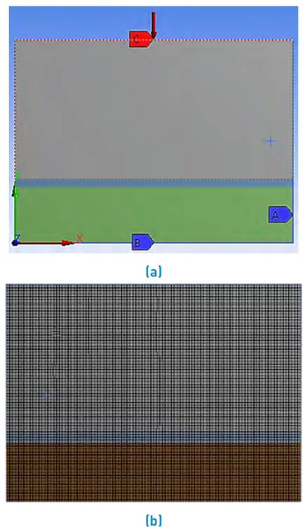
Figure 24 Nanostructured coating:(a)2D CAD model,application of restrictions and reaction forces,(b)mesh
The analysis was performed on a rectangular section with analysis.

Figure 25 shows the results of equivalent stress and penetration.
The coating attempts to penetrate the same tool; these variations in long-term penetration influence the performance of the material and the adhesion to the substrate. As an example of penetration, when cracks are formed in the coating due to fatigue, the coin material penetrates those cracks and comes into direct contact with the punch material; it negatively affects the coining result [7], altering the quality of the final coinage, which is an indication that the coating has fulfilled its working life and that the coining tool must be replaced. Figure 26 shows the results of X-deformation and Y-deformation. As the analysis represents a cross-section, it is evident from Figure 26(a) that the displacement is concentrated towards the positive side of the section. The displacement to one side indicates a continuation of the materials and represents a behavior close to the coating’s reality. Figure 26(b) shows that the displacement is concentrated in the lower part, in the vicinity of the contact between the test materials. The orders of magnitude in the displacement results are minimal; consequently, it is challenging to find equipment to visualize the results physically. Therefore, the results can be considered ideal, without forgetting that more studies can be carried out through other analysis methods in which more results of the behavior of the coatings are obtained. Figure 27 shows the results of the slip distance of the axisymmetric 2D analysis. In the sliding distance„ it is clear that edge effects can be generated in the tool with a linear behavior, as it was proposed 100 μm of section width; the diameter is equal to 200 μm, with a maximum displacement of 1.87 × 10⁻⁸ mm. Then for the standard diameter of the punch equal to 22 mm the maximum displacement is 2.06 × 106 mm, in general features, the coating presents a suitable behavior. Finally, a rendered CAD model with its respective final assembly is presented, see Figure 28.


7. Conclusions
The CAD-CAE design allowed the development, analysis, and selection of suitable materials for each mechanical press component; the design approach allows an easy understanding of its operation. The FEA analysis also allowed for an iterative evaluation of the structural framework and the proposal of other components. The safety factor applied for designing the most critical elements of the machine was 4, but for the machine in general, it was considered a safety factor ≥ 2, ensuring the machine’s resistance to overloads and providing the required confidence.

For the test sheet, a rail-mounted displacement system driven by lead screw actuators was designed. This system adds versatility to the sheet, giving it the advantage of moving freely so that impact loads are distributed over the entire sheet area and better visibility of the tests, greater control over the coining depth, and general testing. Since the impact is received directly by the test sheet, the displacement system will be subject to minimal vibrations that do not affect its operation. For the coating FEA analysis, an axisymmetric 2D model was generated applying Saint-Venant’s principle of load distribution. This principle allows us to understand how the stress results may or may not be affected according to the load application’s distance. The results with an approximation of the behavior of the coating on a real scale are satisfactory and stimulate the development and generation of new research.

