


 Inglés (pdf)
 Articulo en XML
 Referencias del artículo
 Enviar articulo por email
 Citado por SciELO
  Citado por Google
  Similares en
SciELO
Similares en
SciELO  Similares en Google
 Permalink
I. INTRODUCTION
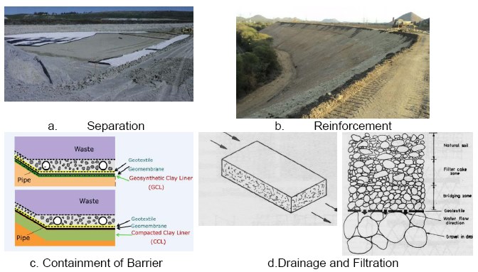
Geosynthetic, a man-made material generally available in the form of geogrids, geonets, geotextiles, geopipe, geofoam and geomembrane. Depending upon the requirements, Figure 1 shows the main function of the geosynthetic material [1]: a) Separator: When placed between two different materials and provide long-term stress barrier; b) Reinforcement: For stabilising the soil to provide better tensile strength; c) Containment of Barrier: To prevent the leachate in a landfill; d) Filtration: For retaining fine particle on its upstream, and, Drainage: Allows fluid flow through the material.
With the increase in population, the road traffic has tremendously increased. The increase in vehicle movement generate high vertical load to the subgrade soil and in soft to medium soil conditions, the soils were unable to withstand the vertical pressure excited by the wheels; this leads to failure or formation of cracks in the pavements. In flexible pavement, the stress developed on the paved road can be reduced by placing the Stress Absorbing Membrane Interlayer (SAMI) which provides a tensile force to reduce the crack; apart from increasing the bearing of the road, it also reduces rutting [2, 3]. Figure 2 shows the reduction of cracks paved road with and without geosynthetic. Geosynthetic is also used as a separator to prevent fine soil migrating into base-course and further layers [4].
Field study, laboratory study and numerical studies emphasised the use of geosynthetic material in pavement of soft clay and dense sand ground [5, 6, 7, 8, 9, 10, 11, 12, 13, 14]) under static loading and literature shows the importance of geosynthetic under cyclic loading to reduce the vertical stress and deformations [15, 16, 17]. This man-made material can also be used under foundation [18, 19, 20] to increase the bearing capacity of the soil.
Form the above study, it was clear that geosynthetic material reinforces the soil to give increased bearing pressure. To have a comparative study between the geosynthetic materials, a laboratory study was conducted to understand the influence of various geosynthetic material say geogrid, geotextile and geomembrane in CBR value. However, geomembrane used as a separator was considered for comparative study. Cost analysis was also carried out for the optimum condition.

II. MATERIALS AND METHODS
A. Material property
The soil used was collected from Thadagam Road, Coimbatore, India and its various index and physical engineering properties of the soil were tabulated in Table 1 using Indian Standard codes [21, 22, 23, 24, 25]. The properties of the geosynthetic were tabulated in Table 2.


B. California Bearing Ratio (CBR)
California bearing ratio was conducted as per IS 2720 – part 16 [26] in a 155 mm diameter and 175 mm height. The soil was prepared at optimum moisture content for a disturbed sample under dynamic compaction to a height of 125 mm and surcharge plate was placed during loading. The test was conducted for both unsoaked and soaked for 4 days’ condition. The bearing ratio was found using equation (1); the value of 2.5 mm penetration and 5 mm penetration was calculated. For 2.5 mm penetration, the standard load is 1370 kg and for 5 mm penetration, it is 2055 kg.
 (1)
(1)
C. Parameter study
California bearing ratio (CBR) tests were carried with geogrid, geotextile (non-oven type) and geomembrane and compared with results of soil alone. Table 3 shows the parametric study involved.

D. Sample preparation
The fine-grained soil of 4.5 kg was mixed with an optimum moisture content of 14% was dynamically compacted in five layers with 56 blows by a hammer weight of 4.89 kg. Geogrid, geotextile and geomembrane were cut to the diameter of the mould. For single layer, the material it was kept at the middle of the mould, for two spacing it was placed at a 1/3rd height and for three-layer it was placed at a 1/4th height of the mould (Figure 3).

III. RESULTS AND DISCUSSION
Load corresponding to 2.5 and 5 mm for unsoaked condition was 38.57 and 49.09 kg respectively; the corresponding CBR value was calculated as 2.82% and 2.38%. The CBR value was observed for soaked condition for 2.5 and 5 mm penetration was calculated as 2.3 and 2.21 for a load of 31.56 and 45.59 kg respectively. There was a reduction in CBR between unsoaked and soaked condition was by 18.44 % and 7.14% for 2.5 and 5 mm penetration respectively; as 2.5 mm penetration value was higher than the 5 mm value the former value was considered for CBR calculation (Figure 4).

A. Influence of geogrid
The geogrid was placed at the mid of the CBR column and loaded till 14 mm penetration. A comparative representation was shown in figure 5 for an unsoaked and soaked condition for various geogrid conditions. There was increase in CBR value increases to 58.18%, 78.44% and 79.31% for single, double and three layers respectively. The increase in bearing ratio was doubled with the introduction of geogrid in the soil for a single layer. For two and three layers of geogrid, the CBR value was increased to 73.44 % and 79.31% respectively. The difference was less between two and three layer as the stress overlap between the segregation of soil layers and geogrids.

B. Influence of geotextile
Geotextile was also placed in mid as single, two and three layers. There was an increase in bearing ratio by 50.09%, 67.7% and 77.08% when compared to unsoaked soil alone. Under soaked condition, the bearing ratio increased to 39.95% and 84.11% for single and two layers; when three layers were placed the bearing had reduced to 76.81%. It was observed that the bearing ratio decreased to 76.81% when three layers of geotextile were placed (Figure 6).

C. Influence of geomembrane
The geomembrane when placed in middle of the mould, the bearing ratio increases to 58.18%, 73.44% and 79.31% under unsoaked condition when compared to virgin soil. After soaking it, the CBR value increases to 39.51%, 84.11% and 76.81% for different layers (Figure 7).

D. Reinforcement Ratio (RR)
Reinforcement ratio (ratio of the load with the geosynthetic to the load without the geosynthetic material), for unsoaked and soaked specimen there was calculated. Figure 8a shows the RR value for selected penetration level; RR value was high around 2.5 mm penetration and there was a sudden decrease beyond that [27, 28]. It was clearly visible that soaked CBR value with three layers of geogrid followed by geotextile and geomembrane showed maximum value compared to two and single layers of the respective material. However, the maximum CBR value considered for design is limited to 9%.
In Figure 8b unsoaked and soaked RR value was plotted for 2.5 mm penetration and it ranges from 1.66 to 5.09, mostly soaked values were less than that of the unsoaked values expect in case of three layers of geogrids; similar to the observations of Fannin and Sigurdsson [29]. For geogrid it shows higher value because of its stiffer characteristics, followed by geomembrane and then geotextile. As the ratio value was greater than one, it implies that the geogrid material can be used for subgrade material to increase the penetration load characteristics.

E. Cost analysis
As per IRC 37-2000 [30], if the CBR value exceeds 10% the thickness of pavement is not affected majorly. For triple layers of geogrids, the CBR value for unsoaked and soaked value was 13.57 and 11.68 values respectively; hence two layers of geogrids under soaked condition was chosen for design of pavements.
A flexible pavement was designed (Figure 9) and its thickness of each layer was tabulated in Table 4. Cost analysis was done for soaked two layers of geogrids using equation (2) and the following input parameter was considered.
Cumulative number of standard axles to be catered for design (N) in msa:
 (2)
(2)
Where, r- annual growth rate (%), n- design life (years), A –initial traffic (cv/day), D- lane distribution factor, F- vehicle damage factor.


Two lanes single carriageway with 500 cv/day with 7.5% of traffic growth rate per annum with 15 years of design life with vehicle damage factor of 2.5 standard axles per commercial vehicles and CBR value of 8.66% with lane distribution factor as 0.75D. Table 5 shows the break-up of various thickness of layer.
Difference in cost estimation for reinforced and unreinforced subgrade

The data were obtained from Public Works Department estimated cost chart and there was reduction around 8218.63 USD (in percentage = 6.38%).

IV. CONCLUSION
Geogrid and geotextiles were most commonly adopted material to increase the bearing of the soil. The presence of a geosynthetic layer in, or at the bottom of the base can resulted in minimum stress and strain transfer in to the subgrade. In case of flexible pavements, where there is a less stiff subgrade material lies beneath the layer of subbase course, improvement in modulus of the base or subbase layer resulted in improved, more broadly distributed vertical stress on the subgrade. Hence in this study, an attempt is made to study the effect of subgrade layer reinforced with different geosynthetics. Three different geosynthetic materials were selected and reinforced with three types of spacings for reinforcing the subgrade. The geosynthetics were installed at middle of compacted subgrade, double spacing at 1/3rd layer of compacted subgrade, and triple spacing at the 1/4th layer of the compacted subgrade. The following are the conclusions arrived from the study for soaked values mainly,
California bearing ratio of unreinforced soil under unsoaked condition was found to be 2.8 % and under soaked conditions, it’s about 2.3 %, which indicates the poor status of the subgrade material for 2.5 mm penetration and there was a reduction in CBR value by 17.86% for soaked condition compared with unsoaked condition.
The CBR value ranges as 4.86, 8.69 and 11.68 % for geogrids, for geotextiles it ranges as 3.83, 7.17 and 9.93% and for geomembranes 4.35, 5.89 and 8.19 % for single, double and triple layers respectively. Test results shown that, the subgrade layer reinforced with geogrid shows higher CBR values than geotextile and geomembrane for all the reinforcement layers because of its stiffness and the strength characteristics.
When positioning geogrid as reinforcement layer, the apertures in geogrid helps in developing effective interlocking mechanism, holding soil together and improves redistribution of load over a wider area.
The maximum CBR value adopted for designing the flexible pavement is 9%, beyond which there will be no significant reduction in the thickness of the pavement layer. Considering this, geogrid with double layer spacing was considered as the optimum type and positioning of material.
For the unreinforced subgrade CBR value the thickness required as per IRC: 37-2001 was 850 mm whereas when using the geosynthetic material as subgrade reinforcement the thickness was reduced to 540 mm. This reduces the cost of around around 8000 USD amouting to 6.4% compared to the unreinforced soil in pavement.
The reinforcement in subgrade layer resulted in developing adequate stiffening which resulted in reduction of thickness and time of construction. This also helps in increasing the life of the pavement.

