


 Inglés (pdf)
 Articulo en XML
 Referencias del artículo
 Enviar articulo por email
 Citado por SciELO
  Citado por Google
  Similares en
SciELO
Similares en
SciELO  Similares en Google
 Permalink
Introduction
Torque measuring systems mainly consist of a torque transducer and a measurement amplifier and may be used inside laboratories or as part of outdoor setups [1]. In either case, knowing the influence of environmental factors such as relative humidity (RH) on the measuring instruments is central to understanding how they perform [2,3]. The investigation of the effect of relative humidity on the zero signal of a torque measuring system is relevant to determine how it contributes to the error component and drift of the measuring system readings [4]. This can also explain differences between calibration measurements carried out under laboratory and on-site industrial conditions [5,6]. The influence of RH on torque transducers has been considered earlier for inter-laboratory comparisons using a climate-controlled cabinet [7].
Current torque transducers are isolated from the environment such that the effect of RH on the sensing element is minimized [8]. Nonetheless, changes in RH can considerably affect transducer’s sensitivity [9]. Thus far, complicated and extensive methodologies have been used to measure humidity effects, but Bruge [8] proposed a simpler approach measure this effect on torque transducers inside calibration laboratories, with fewer resources and at a lower cost. The effect of humidity on the zero signal of a reference torque transducer in known to vary from + 3.3 to -9nV/V% RH, and the influence of humidity on a DMP40 measurement amplifier, studied at 22°C, was found to vary from 0.27 to - 1.8nV/V% RH [9].
In the present work, the effects of relative humidity on the zero signal of a torque transducer and a DMP40 measuring amplifier were studied under increasing RH conditions at four different constant temperatures. The readings of these two devices were taken when subjected to these experimental conditions either individually or together.
Materials and Methods
Apparatus
The following equipment was used in this experimental work:
A Votsch Stable Climatic Chamber (SCC) (model VC34060,. Germany) with internal dimensions of 0.7 x 0.8 x 0.8 m, a temperature range of 283 to 363 K, and an RH range from 15% to 95%.
An HBMDMP40 amplifier (model DMP40S2,. Germany) with the following settings: filter of 0.2 Hz Bessel, signals reading set to “absolute”, the range of measurement was 2.5 mV/V and the excitation voltage was 5 V. The excitation of the DMP40 amplifier was 220 VAC with 50 Hz.
An HBM BN100A stable bridge calibration unit (Germany). The DMP40 amplifier and the BN100A were connected with a shielded cable.
An HBM reference torque transducer (model TN, Germany), with capacity of 1 kN-m, IP: 20, and an accuracy class of 0.05).
Two sets of humidity and temperature ALMEMO sensors (model FHAD3Rx, Germany). One set was placed inside the SCC and the other outside. The sensitivity of each set was of 0.1% for RH and ± 0.1 K for temperature.
Experimental procedure
In the first measurement round, the DMP40 amplifier was placed outside the SCC while the reference torque transducer was placed inside the SCC. The SCC conditions were set to 40% RH and temperature of 15°C for 12 hours, followed by a programmed RH step-wise increase of 5% every 4 hours until reaching 80% RH. This procedure was repeated at 22°C, 31°C, and 40°C with an initial RH of 35%. The following measurement cycle was done as already explained, except that both the DMP40 amplifier and the torque transducer were placed inside the SCC. Finally, the third measurement cycle proceeded as in the previous two, but the DMP40 amplifier was placed inside the chamber and the BN100A unit outside.
The BN100A calibration unit was set to an excitation voltage of 0 mV/V, which is the nearest point to the observed torque transducer zero signal (0.012130 mV/V). Warm up times for the DMP40 amplifier and the BN100A calibration unit were recorded, and so the time needed for the DMP40’s low pass filter to work. All of the experiments were conducted under controlled environmental conditions with stabilities of ± 1 K and ± 5% RH outside the chamber, and ± 0.1 K and ± 0.5% RH inside the chamber. All measurements were repeated three times. These measurements were employed to assess the effect of the evaluated experimental conditions on the RH readings, reflecting the difference between the DMP40 amplifier readings at each RH value of and the readings taken at initial RH conditions, namely the response difference (nV/V) for the three measurements.
Results and Discussion
The effect of humidity on the readings of the torque transducer and the DMP40 amplifier was proportional to the increase in temperature and humidity conditions to which these devices were subjected (individually and together) during the experiments (Fig. 1a - d). Throughout the four tested temperatures (15°C, 22°C, 31°C, and 40°C), the readings of the DMP40 amplifier, when exposed to experimental conditions alone, were the least affected by the controlled RH increase, whereas the readings of the transducer, when exposed to experimental conditions alone, were affected by RH with reading values increasing in a linear fashion. Interestingly, the effect of increasing RH was less pronounced on the two devices tested together than on the transducer alone.
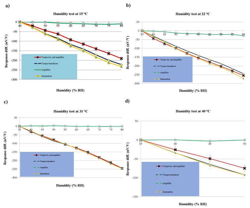
Figure 1 Effect of controlled, changing relative humidity conditions on the readings of a DMP40 amplifier and a torque transducer when subjected to experimental conditions separately and together at temperatures of a) 15°C; b) 22°C; c) 31°C; and d) 40°C.
Moreover, the summed effects of each treatment on the readings of the DMP40 amplifier and the transducer were slightly more pronounced than those of the transducer alone. However, temperature played also a role in eliciting this effect response (Fig. 1c). For instance, at 31°C the differences between combined effects of the transducer and amplifier (subjected together to experimental conditions) and the sum of independent effects of the two devices were indistinguishable. This is likely due an influence of RH on the amplifier smaller than the influence of RH on the transducer itself. The measurements at 40°C shown in Fig. 1d were carried out with a maximum RH of 50% since the transducer’s specification state that at a temperature of 40°C, RH must not exceed 50%.
The x-axis is the % RH and the y-axis is the effect of the evaluated experimental conditions on the RH reading, expressed as the difference between the DMP40 amplifier readings at each RH value of and the reading taken at initial RH conditions for the three measurements. Inset legend: i) torque transducer and DMP40 amplifier both inside the chamber; ii) Torque transducer inside the chamber and DMP40 amplifier outside; and iii) torque transducer outside the chamber and DMP40 amplifier inside.
The following simple linear relationship can be used to predict the influence of increasing humidity at a given ambient temperature at only one humidity step change.
R = K x H (1)
Where R is the amplifier/transducer response change in (nV/V), K is the amplifier/transducer humidity coefficient in (nV/V)/(%RH) and H is the humidity change in (% RH). As shown in Table 1, the humidity coefficient K (nV/V)/(% RH) varies from -5.5 to -6 for the transducer, from 0 to -0.6 for the amplifier, and from -4.8 to -5.6 for the transducer and amplifier together. The values provided in Table 1 are useful for those who employ similar transducers and amplifiers, individually or together, in work setups where humidity is not controlled and during long-term measurements or performance testing where surrounding humidity differs among setups.
Table 1 Humidity coefficient (K) values for the transducer alone, the amplifier alone, and both devices subjected to controlled humidity changes across different temperatures.

Most of the added effects of RH on the measurements of the DMP40 amplifier and the torque transducer were slightly greater than the effects on both devices when subjected to humidity changes together (Table 2). This is likely due to humidity on the connecting wires. Therefore, it is recommended to assess humidity effects on the amplifier and the torque transducer together, thus minimizing one the sources of uncertainty in the measurements. Moreover, this difference could be negligible in most industrial applications, such as in the calibration of torque testing machines, within their uncertainties, but it could also be significant in high accuracy measurements such as international comparisons, performance test or research activities.
Table 2 Relative differences between the summation and the experimental results of the DMP40 amplifier and torque transducer when subjected to humidity change separately and together.

The humidity effect is assumed to be the result of a combination of mechanical and electrical changes. Humidity changes can affect the mechanical properties of the both the torque transducer’s strain gauges and the adhesive layers which are used to bond these strain gauges with the elastic member of the transducer. This effect is positively related to the change of the sensitivity of the strain gauge bridges as well as to the time constants of their response. The change of humidity can also affect the electrical charges of the wiring inside the strain gauge system, the transducer, and the measuring amplifier.
Finally, the resulting humidity influence will act exponentially, but not immediately, on the strain gage bridge. From a practical viewpoint, the measuring amplifier is often used with different transducers. Therefore, this investigation could reflect advantageously on torque and force measurements.
Conclusions
From the current experimental work, it can be concluded that (i) the influence of relative humidity on the measurements amplifiers is small, compared to that of torque transducer even at different temperatures. (ii) The summed influence of RH on the amplifier and the reference torque transducer is equal to, or in some cases slightly greater than, the RH effect observed when both devices are subjected to humidity changes together. Therefore, it is recommended to test the humidity effect on the measuring amplifier and torque transducer together. This would prevent from inflating the effect values unnecessarily, thus lowering the uncertainty parameter which can be critical in inter-laboratory comparisons and performance testing. (iii) The humidity coefficient K (nV /V)/(% rH) varies from -5.5 to -6 for the transducer, 0 to -0.6 for the amplifier, and -4.8 to -5.6 for transducer and amplifier together, respectively.

