1. Introduction
Numerous traffic accidents that occur in Colombia often produce complex open bone fractures [1] that are generally treated with external fixation systems. These systems are biomechanical devices intended to restrict relative motion at the fracture site to allow callus formation. They are formed by wires or screws; bridge elements as rails, rods or rings; and clamps to connect the wires or screws to the bridge elements [2]. One kind of external fixator is applied to enlarge bones, to correct defects or to complete gaps in the bone based on the callotasis technique [3]. This can be achieved when one clamp is fixed to a bone fragment and to the rail while another clamp, fixed to another fragment, is moved in a controlled way along the rail [4]. In the commercial system Orthofix, which is used worldwide, the assembly of a clamp onto the rail must be accomplished from the end of the rail. Hence, much time may be wasted during surgery if the system is partially assembled, and then the orthopedic surgeon needs to add or remove a clamp.
The commercial systems used in Colombia are imported and expensive. Previous studies have focused on the development of a fixator for treating injuries, and it was successfully validated in laboratory and clinical tests [5]. However, such a device cannot be used for bone transport. To the best of our knowledge, there is no Colombian fixator that may be used for bone transport.
To encourage and promote the Colombian biomedical industry, this paper presents the design, construction, and mechanical evaluation of a novel bone transport system. One of the requirements of the design was to allow the lateral assembly of the clamps onto the rail to facilitate the mounting process during surgery. Another objective was to define the mechanical analysis and loads, which are not available in the previously published work, and this information can be applied to analyze other designs.
2. Materials and methods
2.1. Geometry and system operation
During the distraction process of bone lengthening, one of the clamps is moved along the rail by the action of the distractor. Since the other clamp remains fixed to the rail and to the other fragment, the distance between the bone fragments at the fracture site increases and promotes the creation of a callus and the lengthening of the bone. Distraction speed depends on the fracture characteristics and the treatment, but it is usually 1 mm per day. In the commercial system LRS Advance (Orthofix, Verona, Italy), the clamps can only be inserted onto the rail from one of the ends, making it difficult to perform further modification of the assembly. The main challenge of the present design was to allow the clamps to be inserted laterally onto the rail.
Two circular ½”-diameter carbon fiber rods were used as the rail. Carbon fiber is recommended for its low density, high stiffness and strength, and transparency to X-rays, allowing inspection during the healing process without dismantling the assembly [6, 7].
The clamp was made of 7075 aluminum (480 MPa yield strength) and is composed of the body, the cover, and the wedge (Fig. 1). The body and the cover have five grooves to contain the screws. Two 6 mm Allen bolts were used to join the cover to the body and fasten the screws. The wedge is used to fasten the clamp to the rail for fixing the axial movement. The clamp can be inserted onto the rail by applying a small deformation to the rods. This prevents the clamp from separating from the rail during distraction and allows axial displacement when the wedge is loose [8]. The wedge can be removed from the system during distraction.
2.2. Mechanical analysis of the clamp
Finite element models were developed to analyze the stress distributions for three load cases. First, the clamp was analyzed under the force applied by the rods during insertion; the second model simulated the clamp when it was submitted to the force generated by the bolt to fix the wedge; third, the clamp was simulated under the action of the service load.
In the model simulating the insertion force (Fig. 2), the symmetry of the clamp with respect to the XZ plane was used and the force was distributed on the contact line between the rod and the clamp (red line in Fig. 2). The dimensions of the clamp were chosen such that the bars had to deflect 0.5 mm to allow clamp assembly. Therefore, the force on the clamp was calculated as the force needed to deflect the midpoint of the bars 0.5 mm, assuming embedded extremes. This force, distributed along the clamp, was equal to 2.1 N/mm. The displacement in the Y direction on the symmetry plane was restricted. Displacement in the X and Z directions was restricted to the grooves in contact with the screws to consider the stiffening effect of the screws. With this model, a maximum von Mises stress of 3.9 MPa was obtained, which is significantly smaller than the yielding strength of the material (480 MPa).
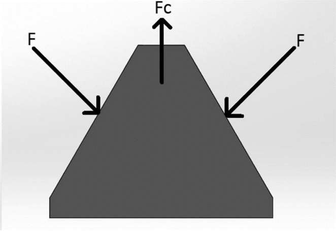
For the second model, the free body diagram of the wedge shown in Fig. 3 was considered, where F are the forces between the wedge and the rods and Fc is the force applied by the bolt that fixes the wedge to the clamp. Fc was calculated as the minimum force needed to avoid sliding between the clamp and the rods when the service load was applied to the clamp. A Newtonian model with a friction coefficient of 0.16 was assumed. Golden and Scott [4] recommend a service load equal to 30% of the patient weight. To obtain a conservative design, a service load equal to 50% of a 100 kg patient was considered in our design. With this load, the minimum force, Fc, to avoid sliding was 571 N. However, the preload recommended for the bolt, calculated as 75% of the proof stress, was 2627 N. Therefore, this value was used to evaluate the stresses on the clamp. Symmetry with respect to the XZ plane was again used and a rod in contact with the clamp was included (Fig. 4). Displacement in the Y direction on the symmetry plane and displacements in the X and Z directions on the grooves for the screws were restricted. The resultant maximum von Mises stress was 22 MPa, which is considerably smaller than the yield strength of the material.
Source: The authors.
Figure 3 Free body diagram of the wedge. F is the contact force between the rods and the wedge and Fc is the force applied by the bolt.
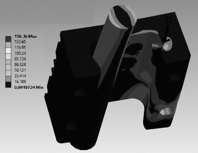
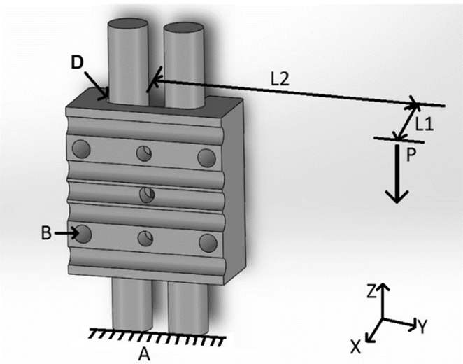
The third model was intended to evaluate the stress distribution in the clamp generated by the service load during distraction. At this stage of the procedure, the clamp is not axially fixed to the bars and the axial movement is restricted by the distractor. This model also contained a portion of the two bars. Thus, the bottoms of the rods were embedded and the action of the distractor was simulated by restricting the axial (Z direction) displacement of point B (Fig. 5). The service load P (500 N) was applied at distances L1 and L2 equal to 18 and 91 mm, respectively, keeping consistent with the geometry of the assembly (Fig. 5). The analysis yielded a maximum von Mises stress equal to 137 MPa at point D (Fig. 5, 6).
Since the stresses found in the three models were smaller than the yield strength of the material, we proceeded with the construction, assembly and mechanical evaluation of the prototype.
Source: The authors.
Figure 5 Load and boundary conditions in the model used to evaluate the clamp with the service load.
3. Method for experimental evaluation of the system
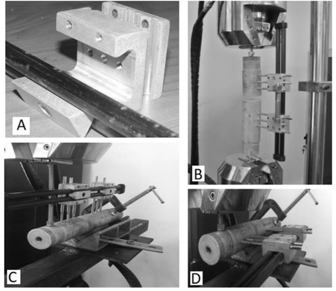
The stiffness of the system under axial loading (Fig. 7); medio-lateral (ML) and antero-posterior (AP) bending (Fig. 8); and flexo-torsion loading (Fig. 9) was evaluated under the ASTM F1541 standard [9]. The gap G between the bone fragments was 20 mm (Fig. 8). The components of the prototype and the test configurations are presented in Fig. 10. For the flexo-torsion test, the load was applied at the end of a 4 mm thick and 50 mm long plate located at the extreme of one of the fictitious bone. Each test was repeated three times with five cycles of load and unload.
Source: The authors.
Figure 10 Prototype. A) Components of the clamp and rail. B) Experimental configuration for axial test. C) Experimental configuration for AP bending. D) Configuration for ML bending tests.
Two clamps were used in each system, with two 3-mm diameter screws per clamp. The distance between the rail and the bone model was 50 mm. Nylon cylinders of 50-mm diameter were used as bone simile. A 5-cm long distractor of the LRS Advanced Orthofix commercial system was used for the tests.
For this application, the number of load cycles is relatively low and fatigue is not critical for the parts; however, cyclic loads may cause slippage between parts. Hence, a cyclic axial compressive test was performed by applying a sinusoidal cyclic displacement with an amplitude of 0.5 mm. To precondition the assembly, a preload corresponding to a displacement of 0.75 mm was applied. Tests were conducted with a servo-hydraulic machine (Reference HT-9711, Hung-Ta Instruments Co. Ltd., Taipei, Taiwan).
The results were compared with those reported for a rail made of carbon fiber [7] assembled with clamps of a Long Model Orthofix commercial system (Fig. 11) and a custom made model (Fig. 12). In addition, the results were compared with the stiffness of the systems ProCallus of Orthofix and Dynamix DFS (Ebifix, Iowa City, IA, USA) (Fig. 13) reported by Burgers et al. [10].
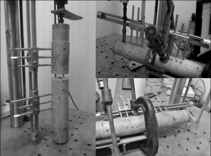
Source: The authors.
Figure 12 Custom made external fixation system used for comparing the stiffness.
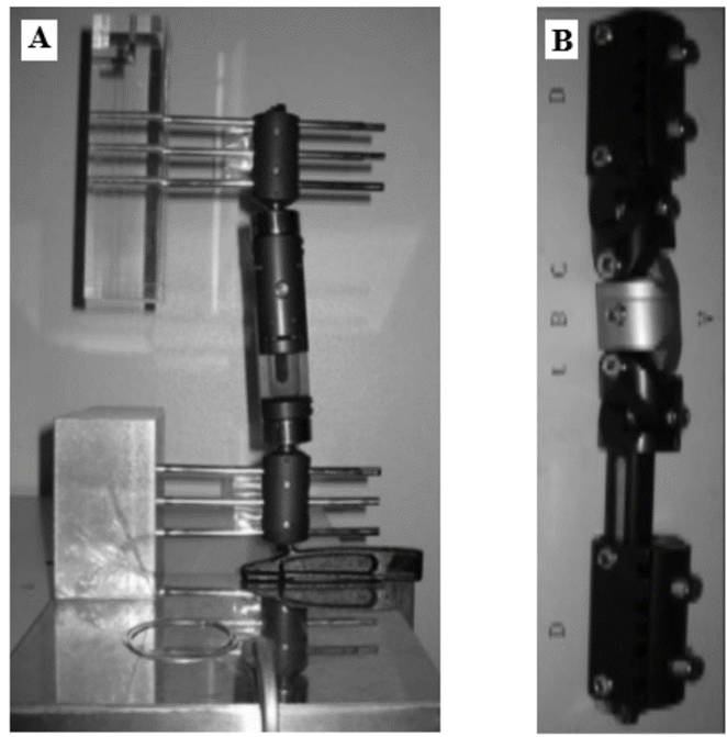
Source: [10].
Figure 13 External fixation system used for comparing the stiffness. A) ProCallus from Orthofix (Verona, Italy). B) Dynamix DFS from Ebifix (Iowa, IA, USA).
4. Experimental results
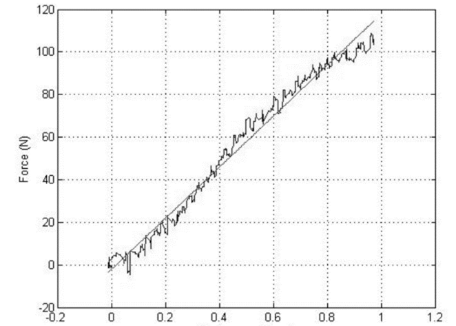
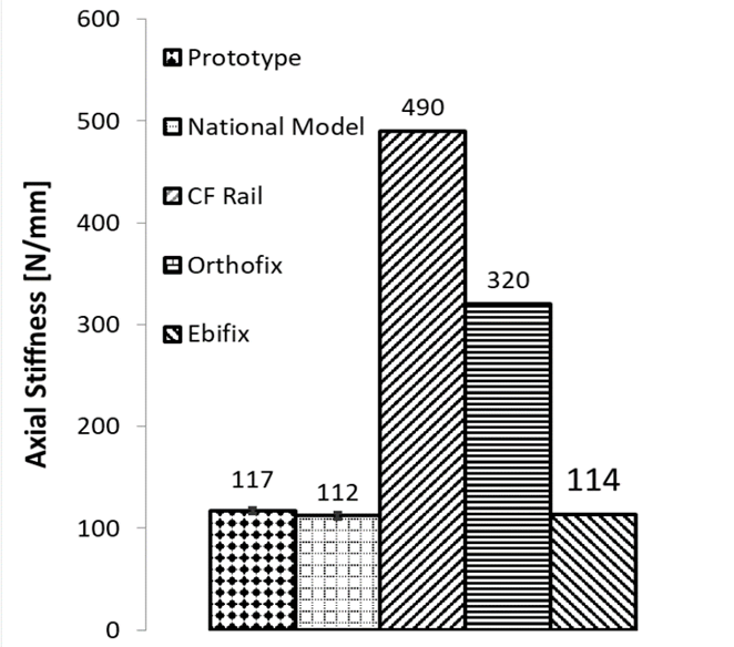
An approximately linear load-displacement relation was obtained in all experiments (Fig. 14). The stiffness of the prototype under axial load (Fig. 15) is similar to those of the custom made and the Ebifix systems but is smaller than the stiffness of the Orthofix and the carbon fiber models. For the other load cases (Fig. 16), the stiffness of the prototype is lower than those of the custom-made model and the carbon fiber model for ML bending and AP bending, respectively. For flexo-torsion loading, the stiffness of the prototype was higher than those of the National model and the CF rail. There were no available results in the literature for the Ebifix or the Orthofix models under flexo-torsion loading.
Source: The authors.
Figure 14 Load-displacement curve for an axial compression test. The green line represents a linear regression of the data.
Source: The authors.
Figure 15 Stiffness under an axial compression load. The bars represent the standard deviation
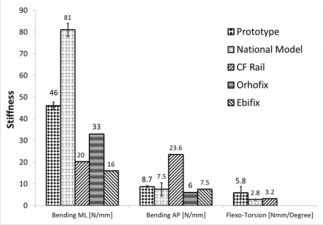
Source: The authors.
Figure 16 Stiffness under medio-lateral (ML) bending, antero-posterior (AP) bending, and flexo-torsion loading. The bars represent the standard deviations.
During the cyclic test, the system was able to sustain the load without slipping during 1000 cycles, as shown in Fig. 17 for the last 20 cycles.
5. Discussion
We developed a new model of an external fixation system where the clamps can be assembled or disassembled laterally from the rail. The clamp can be mounted onto the rail by applying a small deformation to the rods. This design allows axial movement during distraction and restricts lateral relative displacements. The wedge to fix the clamp to the rail prevents axial displacement when no distraction is required. Two commercial carbon fiber rods were used for the rail, which considerably reduced the manufacturing cost and time.
The axial stiffness of the prototype was smaller (117 N/m) than those of the carbon fiber system (490 N/mm) and the Orthofix ProCallus system (320 N/mm) but was comparable to the other evaluated systems (112 N/mm for the custom-made system and 114 N/mm for the Ebifix system). In addition, for the other load cases, the stiffness of the prototype was similar to the Orthofix and Ebifix systems, which are widely used in clinical applications. For some load cases, the Orthofix and the Ebifix systems presented smaller stiffness, which may be attributed to their greater number of components. Finally, the prototype was able to sustain a cyclic force with constant amplitude without slipping.
Even though the system presented a mechanical behavior similar to that of other commercial systems, there is a need to reduce the size of the clamps, which is the next stage of this work.


