1. Introduction
The use of irrigation in vegetable crops is a necessity, even in the rainy season, due to poor rainfall distribution, considering that these crops are quite susceptible to water deficits [1]. The method of drip irrigation is well suited to these crops, as it promotes big savings in water and energy (since water is applied in a more localized form and at low pressures), in addition to improving efficiency in cultivation and requiring minimal workforce.
In Brazil, there is a deficiency of technological innovations in microirrigation to provide self-sufficiency of low-cost technologies mainly adapted to the small-scale producer.
However, the types of microtube emitters used in microirrigation systems appear as an attractive alternative technology to this part for producers, due to the low cost of production and installation. This kind of microtube, also called spaghetti tube, is a long-path emitter made by polyethylene with a small diameter (0.6 to 1.5 mm), and easy to install and maintain.
The authors emphasize that microtube irrigation systems can run without raising the operating costs because they work under gravity or under low pressures. In addition, microtubes can be adapted to different landscapes, including areas where there are large differences in pressure due to topography, because it is possible to compensate the pressure variation by varying the length of the microtubes and, consequently, to obtain high uniform flow along the lateral line.
In this sense, the research group in hydraulics of the Luiz de Queiroz College of Agriculture (ESALQ / USP) is studying the use of the microtube emitter types to increase the technological level and competitiveness of small-scale farmers. Initially, [2] developed software for hydraulic design and evaluated the performance of technology in drip irrigation of vegetables and fruit under conditions of laminar flow. Then, [3] evaluated its use in conditions of turbulent flow. In addition, with more innovative character [4,5], used microtubes as a mechanism for regulation of micro-sprinkler system pressure.
With increasing competition for water and electricity at the various productive sectors there is a need for development of irrigation systems that apply water at small flow rates with high uniformity and low energy requirements, i.e., operate at low pressures. Given the above, the aim of this research was to develop and evaluate, technically and economically, a drip system irrigation with ULF using branched microtubes in a garden of lettuce.
2. Materials and methods
2.1. Location and stages of the research
This research was divided into two stages. The first consisted in the determination of the internal diameter of the microtube and design of the irrigation system with ULF, the second stage was to install the irrigation system in the field, to perform tests to obtain the uniformity of water application, implementation of the lettuce crop, to evaluate the cost of irrigation system with ULF.
The first stage of the experiment was conducted in the Hydraulics Laboratory, and the second stage was conducted in an experimental area of the Biosystems Engineering Department, Luiz de Queiroz College of Agriculture (ESALQ / USP) in Piracicaba - SP at 22º42’S and 47º30’W.
2.2. Determination of the internal diameter of the microtube
The microtubes of green, yellow, orange, and blue color with nominal diameters of 0.6, 0.7, 0.8, and 1.0 mm, respectively, with a length of 15.0 m each was evaluated. The microtubes were subjected to a constant potential load of 1.26 m, corresponding to the unevenness between the water level of the upper reservoir and the end of the microtube.
Through the force of gravity, water from the upper container was brought by the microtube to the lower container with a known weight, during a period of time. This container with water was weighed on an analytical balance. The water volume was calculated by the weight and water density at the monitored temperature.
For each microtube and length, three replications were performed, and in each volume collected, the water temperature was measured to calculate its kinematic viscosity. The reason of this measurement is because the laminar flow is very sensitive to the water viscosity variation, which is influenced by temperature variation.
The internal diameter of the microtube was determined by hydraulic measurements in the laboratory and by the optical profile projector.
The hydraulic determination of the microtube internal diameter was performed according to the methodology proposed by [6]. The test was repeated three times. The internal diameters of the microtubes by eq. (1) were calculated.
where:
D - internal diameter of microtube, m,
Q - flow rate of microtube, m3 s-1,
ν - kinematic viscosity of water, m2 s-1,
Z - potential load, m,
L - length of the microtube, m.
In optical diameter determination, the Optical profile projector (model HB400-2) was used. This equipment indicates in a digital display with 0.001 mm resolution the microtube diameter, in the condition of null hydrostatic pressure. The diameter determination in the profile optical projector used five rings of each microtube with approximately 4 mm length. The mean value of these readings was subsequently used for comparison between the hydrodynamically determined diameter and the one supplied by the manufacturer, which was called the nominal diameter (DN).
2.3. Description of the system of drip irrigation with ULF using branched microtubes
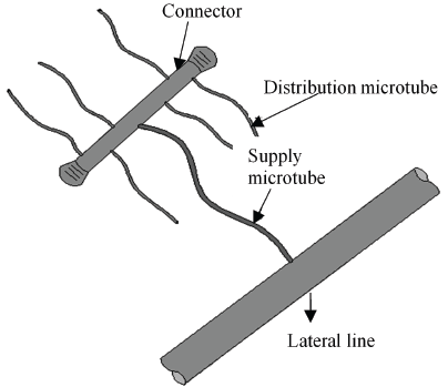
The configuration of the proposed system consists of a lateral line with nominal diameter of 10 mm, a supply microtube (SM) and six distribution microtubes (DM) that are connected to the supply microtube through a connector can be seen in Fig. 1.

Source: The Authors.
Figure 1 System of drip irrigation with ultra low flow rate (ULF) using branched microtubes.
Hydrodynamic diameter value was used as the microtubes internal diameter to develop the design model of the proposed emitter due to the high precision of this methodology.
For sizing of the irrigation system the following values were admitted, initially proposed in the project: flow rate of 0.2 L h-1 for the distribution microtube (diameter 0.888 mm) and 1.2 L h-1 for the supply microtube (diameter 1.074 mm), viscosity of 1.01x10⁻⁶ m2 s-1 for a temperature of 20 °C, pressure head of 14.72 kPa, and pressure of 2.94 kPa in the connector.
The Reynolds number (Re) was calculated by eq. (2) and the friction factor (f) was determined by Hagen-Poiseuille equation (eq. 3). We emphasize the use of this equation because the flow regime is laminar (Re ≤ 2300) according to [7].
where:
V - velocity of water in the microtube, m s-1,
D - diameter of microtube, m, and,
ν - kinematic viscosity of water, m2 s-1.
To calculate the standardized head loss (J) eq. (4) was used.
where:
g - gravity acceleration, m s-2.
In the calculation of head loss (hf) in the supply microtube and distribution microtube Bernoulli equation was used, eq. (5).
where:
The lengths of the supply microtube and distribution microtube were calculated by eq. (6).
where:
L - length of the microtube, m.
This calculation was performed disregarding the local head loss.
The results were inserted in a spreadsheet to calculate the length of the distribution and supply microtubes, as can be seen in Table 1 and Table 2, respectively.
Table 1 Parameters used for determining the length of the distribution microtube.

Re: Reynolds number, f: friction factor, J, standardized head loss, Pc: pressure in the connector, hf: head loss, and, Ld: length of the distribution microtube. * Predefined values.
Source: The Authors.
Table 2 Parameters used for determining the length of the supply microtube.

Re: Reynolds number, f: friction factor, J, standardized head loss, Pi: inlet pressure of the supply microtube, hf: head loss, Ls: length of the supply microtube. * Predefined values.
Source: The Authors
The length of the supply microtube for laboratory tests was calculated, because in the field its length will vary due to head losses that occur along of the lateral line. The design of the irrigation system in the field was performed by the stretch by stretch method, but only the microtube supply had changed its length because it acts as a pressure regulator along the lateral line. The distribution microtube had an unchanged size.
2.4. Installation of the irrigation system in the field
After the design of the irrigation system, construction began for the structural part and then installation at the site. The system consisted of: a water tank elevated to a height of 1.5 m above the level of the beds, used to irrigate four beds, a register for begging and finishing the irrigations, an electronic buoy, developed for this experiment in order to keep the water level constant, a valve solenoid, which regulated the entry of water into the box of water, a filter of 155 mesh screen, and, microtubes.
Some technical requirements were taken into consideration in the planning and implementation of the system, aiming for successful low cost with an ULF for small-scale producers: the system should be composed of components with easy acquisition and installation, enabling the assembly operations and maintenance to be done by the small-scale farmer, and the system should provide a high uniformity of water application.
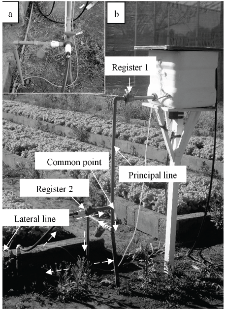
The schema of the irrigation system in the field can be seen in Fig. 2.
2.5. Assays to obtain the system statistical uniformity
The technical viability of the system statistical uniformity (SU) was evaluated before planting and after harvesting the lettuce.
The determination of the uniformity of the flow rate along the four lateral lines installed at the beds was performed by collecting the flow rate in 32 emitters of each lateral line, i.e., for each derivation (with six emitters) an emitter was chosen, totaling 128 emitters evaluated. Due to ULF (0.2 L h-1) of this emitter, each test lasted about an hour, thus, the volume collected enabled the evaluation of the performance of the irrigation system to be achieved.
For better evaluation, three replicates were made. The collected volume in each recipient was determined at the end of the test, using a beaker with a precision of 1 cm3. The coefficient of statistical uniformity (SU) by eq. (7) were determined.
where:
σ- standard deviation of the flow rate, L h-1, and
2.6. Implementation of the lettuce crop
In the field phase, the lettuce (Lactuca sativa) variety "crisp" was implemented with a spacing of 0.3 x 0.3 m in four beds of 1.50 x 15 m existing in the experimental area, where water was supplied from a water tank by gravity to the culture.
The seedlings were produced in styrofoam trays of 12 x 24 cells totaling 768 seedlings transplanted about a month after sowing and each having 2 to 3 pairs of leaves. To each lettuce, an emitter microtube was installed.
The pre-planting manuring with 65 t ha-1 of dung was made. Two applications in coverage of 40 kg ha-1 of nitrogen at 7 and 15 days after transplanting the seedlings was held.
The water electrical conductivity was evaluated (0.25-0.75 dS m-1, at 25 °C) and classified as C2, according to [8]. The values observed were below 0.9 dS m-1, which is the limit value recommended by [8] in order to obtain maximum yield from the lettuce crop. The water pH was measured also, resulting in a mean value of 6.6 which is considered safe for irrigation [8].
The irrigation management was performed based on data from the ESALQ/USP meteorological station. For the estimation of the reference evapotranspiration (Eto), the Penman-Monteith FAO equation was used. The Kc value was obtained for each growing season in accordance with Table 3.
Table 3 Values of the crop coefficient (Kc) for three phases of development of the lettuce crop after transplanting of seedlings.

Phase II - of the transplanting to the following 16 days,
Phase III - of the final of the second phase at 37 days after transplanting,
Phase IV - of the final of the third stage until harvest.
Source: [12].
The harvest of the lettuce was performed two months after transplanting when they showed up ready for consumption. Immediately after the harvest, wet weights of the aerial part of 20 lettuce per bed, chosen at random to quantify the productivity were obtained.
This determination by weighing in balance was made. The authors emphasize that, although productivity does not depend exclusively on irrigation, this is essential information for the qualitative evaluation of the system performance.
2.7. Cost of the irrigation system with ULF
Aiming to spread this technique among small-scale producers, the investment cost of the irrigation system proposed was presented. This cost was compared to a kit of drip irrigation for family agriculture available in the market. The price of this kit was informed by the company.
3. Results and discussion
3.1. Microtube diameter
The results obtained in the hydrodynamic test were 0.762, 0.695, 0.887, and 1.100 mm for the manufacturer's nominal diameters of 0.6, 0.7, 0.8, and 1.0 mm, respectively.
The microtube diameter values obtained by the profile optical projector are in Table 4. The average values of the diameters determined by hydraulic method and optical profile projector were very similar. [9] comments that the diameter measured by hydraulic method is more representative compared to the profile optical projector because the microtube length used to determine the internal diameter is greater when using the hydraulic method.
[2] evaluated the diameters of four microtube tubes in the profile projector and found values different from those observed in this study (0.679, 0.695, 0.820, and 1.024 mm). [10] performed the same study and found internal diameter values of 0.617, 0.698, 0.890, and 1.072 mm. This shows that to determine the real internal diameters it is necessary to obtain greater precision in the design of irrigation systems using microtubes.
The percentage differences between the nominal diameter supplied by the manufacturer (DN), the diameter mean values of the microtubes obtained hydrodynamically (DH), and by the optical profile projector (DP) are presented on Table 5. The largest difference was -27.00% between nominal and hydrodynamic diameter as well as between DN and average value obtained by profile optical projector. In addition, the yellow microtube, which should have DN of 0.6 mm, presented a value of 0.762 mm in both the hydrodynamic method and the optical profile projector, i.e., a value well above that informed by the manufacturer. This exceeded the green microtube diameter which has nominal diameter of 0.7 mm. Both in the hydrodynamic tests and the profile projector the green microtube diameters of 0.695 and 0.666, respectively, were obtained. As a result, the difference between them was -0.14%. In general, the smallest percentage differences were identified between DH and DP.
Table 4 Internal diameter of microtubes measured by profile optical projector.

DP: standard deviation, CV: coefficient of variation.
Source: The Authors.
3.2. Functioning of the irrigation system with ULF
After installation of the system, it was verified that it was not working properly. Only a few drippers were emitting water, this can be due to the accumulation of air in the tubing, and as the inlet pressure was very low, it may not have been sufficient to expel the air pressure. So, it was necessary to make an adjustment in the system by connecting the system to the other input of water, with a pressure of 147.15 kPa, i.e., 10 times higher than the feed pressure previously established.
For proper operation of the irrigation system, it was first necessary to connect it under higher pressure until the expulsion of air present in the tubing (for approximately 1 minute) through of the register 2 and then the inlet pressure of the system was change to 14.72 kPa (register 1). Every time it was necessary to connect the irrigation system this was repeated (Fig. 3).

Source: The Authors.
Figure 3 Top view of the register 2 in which water passed with high pressure (a), view of the direction of water flow in components that allowed the use of high pressure at the start of the irrigation (b).
The dashed arrow shown in Fig. 3 indicates the direction in which the water ran with higher pressure. The common point indicates the location in which both the water from a higher pressure and lower pressure coming from the water and, from this point, the direction of the path of the water is equal regardless of the pressure in which the system operates.
3.3. System statistical uniformity
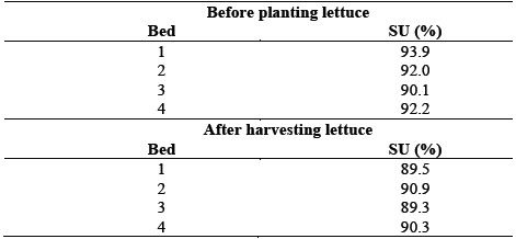
Table 6 shows the results obtained in the evaluations of statistical uniformity. According to the classification criterion of the values of SU for microirrigation system proposed by [11], values equal to or above 90% are excellent, values between 80 and 90% are very good, values between 70 and 80% are regular, values between 60 and 70% are bad and values less than 60% are unacceptable. In the first evaluation, the value of statistical uniformity was greater than 90%. In the second evaluation there was a decrease in the values of uniformity in all the beds due to the presence of some partially clogged emitters. With the exception of the beds 1 and 3, it is observed that the system showed more than 90% of SU in this assessment.
Table 6 System statistical uniformity, before planting and after harvesting lettuce.

Source: The Authors.
According to the classification criteria of the values of statistical uniformity for systems of microirrigation proposed by [11], the performance of the system can be considered excellent, given that the average SU of the four beds was 92 and 90% for evaluation before planting and after harvest lettuce, respectively.
3.4. Productivity lettuce crop
The average weight of harvested lettuce was 512.6 g, which corresponds to a productivity of 57.0 t ha-1. At the beds of numbers 1 and 4 similar productivity were obtained but their values were below beds 2 and 3 which had a productivity of 61.5 and 65.7 t ha-1, respectively (Fig. 4).
This may have occurred because bed 4 is located near the greenhouse that at specific times caused shading, getting a shorter period of light energy and thus causing a reduction in the production of lettuce. Furthermore, the lettuce plants suffered bird strikes during the experiment, and the bed number 1 was most affected.
According to [12], the lettuce yield varies from 15 to 30 t ha-1, i.e., the values presented are well above this range. Considering that this result cannot be attributed entirely to the use of the irrigation system, it was proven that it is possible to achieve high productivity with this technique.
3.5. Costs of the irrigation system
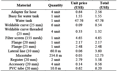
The total cost for the implementation of the irrigation system with ULF using microtubes was US$ 91.70. The water tank is 52.1% of the total cost (Table 7). Because of this, it is recommended to make the maximum use of this material, irrigating the largest possible number of beds, using only a water tank, reducing the cost per unit area.
Table 7 List of components used in irrigation systems and their costs.

US$: American dollars.
Source: Local companies.
The cost of the irrigation system with ULF using microtubes was compared with a kit of drip irrigation for family agriculture, whose value is US$ 227.00 (indicated to irrigate 500 m2). However, the water tank is not included in this kit so it is necessary to add the value of the reservoir, totaling US$ 274.76. For the ULF system to be compared with the irrigation kit, a new calculation was performed, with the proposed irrigation system adapted to irrigate 500 m2, resulting in a total cost of US$ 180.59, i.e., the use of this system provides a saving of 34.3%.
4. Conclusions
The proposal for the use of an irrigation system with ultra low flow rate (ULF) using microtubes can be an economically viable alternative due to low investment and operational cost of the system.
The irrigation system with ULF showed a statistical uniformity that is considered to be excellent.
For this system to be technically feasible, we should perform larger studies to reduce the problems of accumulation of air and clogged emitters, recorded during the experiment.
A high productivity of lettuce crop was obtained using the irrigation system with ULF.


