1. Introduction
AISI 316L alloy is an ultra-low carbon stainless steel with a nominal chemical composition of Nickel, Chromium, Molybdenum, and Manganese. These elements increase the resistance to corrosion, improves the response to pitting in chlorinated environments, and provide greater hardness at high temperatures. Several investigations have focused their studies on increasing the useful life of the materials, with the purpose of decrease the loss material exposed to wear and corrosion. This phenomenon can be achieved by modifying the surface of the material through the application of different types of thermal or thermochemical treatments. These treatments produce thin layers that modify the mechanical and chemical properties.
The powder-pack boriding process (PPBP), is a hardening process where boron powder particles diffused on the surface of the materials. The diffusion of small size boron particles can generate layers composed of one or two-phases (FeB, Fe2B), a diffusion zone, and the base material (substrate) [1,2] These layers increase the mechanical and chemical properties of steels (i.g. wear and corrosion resistance), enhance the life on mechanical components exposed to corrosive, thermal, and abrasive environments [3,4]. The PPBP can be applied in ferrous, non-ferrous materials, and superalloys. In the case of ferrous materials, the boron particles diffuse on the surface of the material filling the interstitial empty spaces of the crystalline lattice of the substrate, generating a single-phase (FeB) or a two-phase (FeB-Fe2B) layer. Boron based coatings have been used in industrial and biomedical sectors due to the high resistance to friction, wear, and corrosion [5-7]. The growth kinetics of the layers is directly associated with the temperature and time of exposure. These conditions can be changed between 1123-1273 K and 1-10 h, respectively; Obtaining layer thicknesses between 30-200 μm, which depends on the properties and characteristics of the base material. Thus, PPBP is the most convenient medium to perform this type of treatment [8].
Reyes Helguera, in 2018, evaluated the tribocorrosive behavior of the borided AISI 316L alloy, during the PPBP at 1273 K for 4 h was used to obtain a total layer thickness of around 50 μm, composed by a two-phase layer (FeB-Fe2B) [9-11]. Also, during tribocorrosion tests, the samples were exposed to a saline solution (Hank's solution) that simulates a body fluid, using the Bruker UMT-2 commercial equipment, following the guidelines of the standard G119-9. The results showed an increase in the tribocorrosive properties of the borided AISI 316L alloy, improving the mechanical strength of the material due to the formation of the bi-phase layer. That could be seen in a reduced material loss caused by the action of wear-corrosion compared to untreated AISI 316L alloy. On the other hand, Campos-Silva, et al. [12] presented new results on resistance to tribocorrosion and cytotoxicity in a bilayer FeB-Fe2B obtained in the PPBP on the surface of AISI 316L alloy under the same treatment conditions. Additionally, they evaluated the in vitro cytocompatibility of the FeB-Fe2B bi-phase layer of the treated and untreated AISI 316L alloy. The results showed that the presence of FeB-Fe2B in the AISI 316L alloy improves the tribocorrosión resistance 1.5 times greater than the untreated material.
Moreover, to reduce the stress on CoB-Co2B bilayer, Delgado-Brito, et al. [13] performed a diffusion annealing process (DAP) to estimate the indentation properties of a Co2B layer using the sensed microindentation fracture toughness Vickers test, obtaining new Kc results for the single-phase layer. On the other hand, Campos-Silva, et al. [14] performed interfacial microindentation tests using a Vickers-type indenter to estimate the adhesion of the coating of the FeB-Fe2B bilayer generated on the surface of the borided AISI 316L alloy. The load applied, Young’s modulus, hardness, and lateral longitude of the cracks generated, alongside the thickness of the FeB layer, were used to estimate the tenacity to apparent fracture and interphase adhesion of the FeB-Fe2B bi-phase layer.
The main objective of this study is to determine some mechanical properties borided layer formed on the surface of AISI 316L alloy to characterize the resistance to wear in terms of the H/E ratio. The samples were studied by sensed indentation Vickers test, optical microscopy, and X-ray diffraction (XRD) analysis.
2. Experimental procedures
2.1. The powder-pack boriding process
Samples with a diameter of 20 mm and 4 mm thick were used in this work. The nominal chemical composition for AISI 316L alloy in (wt%) is 0.03 C (max.), 2 Mn (max.), 2-3 Mo (max.), 10-15 Ni (max.), 16-18 Cr (max.), 1 Si (max.), 0.03 S (max), 0.04 P (max), and Fe as balance. [15]. The samples were embedded in a closed cylindrical case, which contained a GIS® mixture composed of 70% SiC, 20% B4C and 10% KBF4, and particle powder size of the mixture around 50 μm. The boriding process was performed at 1273 K for 4 h of exposure in an oven without the use of an inert atmosphere. Once the treatment was completed, the container was removed from the oven and cooled to room temperature. Then, a borided sample was cut in cross-sectioned for the metallographic preparation, and subsequently, a measurement of the layer thickness of the surface to the substrate was observed in a light field by optical microscopy using the Olympus GX51 equipment. In this process, approximately one hundred measurements were taken in different sections of the sample to estimate the thicknesses of FeB and Fe2B the layers. The thicknesses of the total layer (FeB+Fe2B) was around of 56.82±0.2 μm.
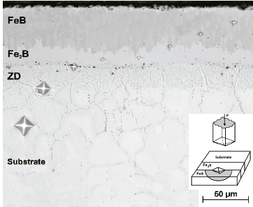
Fig. 1 show the cross-section view on borided AISI 316L alloy, where the flat layer morphology can be observed due to the influence of alloying elements [11].
Source: The Authors.
Figure 1 The cross-sectional view of borided AISI 316L alloy exposed to the PPBP at 1273 K for 4 h.
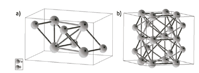
The morphology, growth, and composition of the phases generate by PPBP, are influenced by the alloying elements of the reference material. In pure irons, low and medium carbon steels, the morphology of the layers is intrinsically sawn; however, when the carbon content or other alloying elements increase, the sawn and thickness of the borides layer decrease. Additionally, high concentrations of nickel and chromium, greater than 9 and 6 wt%, respectively, promote the formation of borided with flat layers [16]. The preferential growth of both intermetallic compounds (Boron-Substrate) is given in the crystallographic direction [001] because the density of the boron atoms is preferential in this direction [11]. The layer consist of the FeB phase with approximately 16.2 wt% boron, with an orthorhombic crystal structure (Fig. 2a) and the phase Fe2B with an approximate content of 8.83 wt% of boron and tetragonal structure (Fig. 2b) [17,20]. Bernabé-Molina [16], mentions the main elements that constitute the stainless steels and their influence during the thermochemical treatment of boriding. The Cr, Mo, Mn elements modify the structure and properties of iron and boron compounds; higher chromium content results in a decrease in the thickness of the layer, as well as the sawn structure. Also, nickel dissolves in Fe2B, and in some cases, it causes the precipitation of Ni3B, aiding the layer thickness homogenization. Higher nickel concentration, decrease the layer thickness, and flat the layer-substrate growth interface.
Source: [9].
Figure 2 a) Orthorhombic unit structure of the FeB phase. b) Unit structure of tetragonal shape centered on the body of the Fe2B phase.
According to the bibliography, the phases FeB and Fe2B have very similar tribological properties. Table 1 show some mechanical and chemical properties.
2.2. The sensed Vickers microindentation test
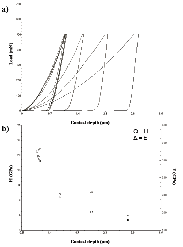
The cross-section of the borided AISI 316L alloy was indented with a commercial indenter (Bruker UMT-2 equipment), which has a Vickers diamond tip. For the indentation load used, load-displacement curves were recorded automatically with the help of the CETR software. In this test, a load of 500 mN was applied for the overall indentations made from the surface to substrate every ~9 μm, and at least three times, the tests were repeated. Fig. 3a and Fig. 3b showing the curves and points of H and E obtained for the borided sample.
Source: The Authors.
Figure 3 Vickers test results a) Curves of load Vs. Displacement, b) Points of hardness and Young´s modulus.
Finally, X-ray diffraction analysis (XRD) was performed on the surface of borided samples to verify the phases formed. The commercial Bruker D8 equipment with radiation CuKα to λ=0.15418 nm, a voltage of 40 Kv, amperage of 25 mA, a scan between 20 and 80° every 5°, a speed of 0.6 θ/s, and the regulate procedure of scanning 2θ - θ.
2.3. Residual stress calculation
The residual stresses (σr) in the iron boride layers were estimated using the Eq. 1 proposed by Totten et al. [23], taking into account the thermal expansion coefficients of each phase.
Where αc is the thermal expansion coefficient of each phase equal to FeB=11.5×10⁻⁶ K-1 and Fe2B=8.75×10⁻⁶ K-1, αs is the thermal expansion coefficient of the AISI 316L=13×10-6 K-1, T1.is the cooling temperature (ambient temperature equal to 303 K), T2 is the treatment temperature (1273 K), υc is the Poisson ratio of the coating, and E is Young’s modulus experimental of the coating.
The value of the Poisson ratio (υc) was calculated considering the Eq. 2 proposed by Bhushan [24]:
Where υi is the indenter Poisson′s ratio equal to 0.07, Ei is Young’s modulus of the indenter equal to 1141 GPa, and Er is the reduced Young’s module experimental.
2.4. Sliding reciprocating test
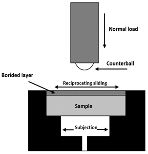
The dry sliding wear tests on the borided AISI 316L alloy were performed at room temperature on a UMT-2 universal tester (Bruker) using a ball-on-flat configuration (Fig. 4), according to parameters of ASTM G113-05 standard procedure with the following conditions: sliding distances of 50 and 150 m, a constant applied loads of 5 and 20 N, and a sliding speed of 30 mm/s. Before the tribological tests, all samples were slightly grounded with abrasive paper and then polished with 0.05 μm Al2O3 powder. Alumina balls with a diameter of 6 mm (E=350 GPa, Poisson's ratio υ=0.3) and highly polished surface finish were used as a counterpart material. The mechanic parameters for the experimental conditions of the wear tests are summarized in Table 2. For the overall experimental set, the friction coefficient (CoF) was continually recorded with the aid of the CETR Bruker software; each test was replicated at least three times for all the experimental set.
Source: The Authors.
Figure 4 Schematic diagram of the linear reciprocating wear test using the UMT-2 tribometer.
Table 2 Contact mechanics parameters obtained for the experimental conditions on the borided AISI 316L alloy.

Source: The Authors.
After the wear test, wear rate (k) was estimated by Eq. 3 [25]:
Where P is the applied load, S is the total relative distance, and the V is the wear volume emanated over the surface of the worn tracks, was estimated using a non-contact surface profilometry (Contour GT-K 3D, Bruker instrument).
3. Experimental results
3.1. The microstructure of the Iron boride layers
The formation of iron boride FeB/Fe2B is a consequence of the high boron potential at high boriding temperatures and the influence of the alloying elements; when an adequate concentration of boron is reached at specific points on the surface of the iron alloy, the Fe2B crystals begin to nucleate and create a surface layer composed of Fe2B and FeB, then a diffusion zone appears in the form of peaks with the presence of chromium and molybdenum, these elements act as diffusion barriers at the interface of the borided substrate layer, alongside a reduced amount of carbon, silicon, and boron [22,24], creating a thin flat layer. Also, the development of the diffusion zone is due to the massive precipitation of Fe outbreaks without coalescence and the presence of products rich in Cr and Si-Mo compounds that grow along the grain boundaries in a preferred crystallographic orientation [001] of the anisotropic crystals in the boride layers (Fig. 5). The preferential growth of FeB/Fe2B is in the direction of the substrate. High score plus software was used to found the present phases [25-28].
3.2. Instrumented indentation Vickers test results
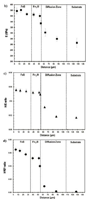
The Young's modulus and the hardness of the boride layer were obtained along the cross-section of the borided AISI 316L obtained by sensed microindentation Vickers test. Fig. 6a shown hardness values in the range of 21 to 19 GPa (for FeB) and 18 to 16 GPa (for Fe2B), till obtaining a value of 4.5 GPa in the substrate.
Source: The Authors.
Figure 6 The behavior of the a) hardness, b) Young’s modulus, c) H/E ratio, and d) H3/E2 ratio along the cross-section of the iron boride layer.
The Young's modulus is related to the trace size effect obtained during the sensed microindentation test [29, 30]. Also, this value was obtained from the Vickers sensed micro-hardness test. Table 3 show an E value for the FeB phase from 381 to 366 GPa, and in the phase Fe2B an E value of 365 to 334 GPa is recorded until obtaining a value of 280 GPa in the substrate as shown in the Fig. 6b.
The wear resistance of a material can be evaluated through the plasticity index (H/E ratio). The plasticity of a material is the property to deform permanently and irreversibly when subjected to stresses above its elastic range. According to Fox [31], higher values of the plasticity radio, the wear resistance of a material decreases considerably. Fig. 6c shown the behavior of the plasticity index (H/E ratio), along the cross-section profile of the borided AISI 316L alloy, which was obtained from the results of the sensed Vickers microindentation test value of 0.056 and 0.049 for the layer. Also, when the value of H/E is closer to the value of 0.1, the material has excellent wear properties. The contact pressures must be less than the yield stress (σf=H/3) of the material; generally, for this type of layer, the contact pressures (Po) do not reach a value higher than 2.5 GPa (σf>Po). In this case, yield stresses in the cross-section were between 7.01 to 1.50 GPa for the FeB layer to the substrate, respectively.
Fig. 6d shown the behavior of the plastic deformation resistance (H3/E2), in a range of values from 0.065 to 0.058 GPa for the FeB phase. Subsequently, these values descend to a range of 0.052 to 0.040 GPa for the Fe2B phase, and finally, in the diffusion zone, the substrate value decreases significantly until reaching the value of 0.001 GPa. In general, these values indicate that PPBP samples have good resistance to plastic deformation in the layer associated with behavior to avoid adhesion failures of the ceramic layer and high wear resistance.
3.3. Residual stress results
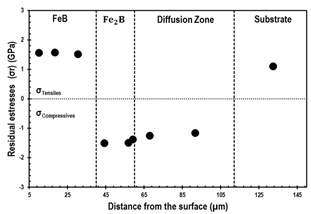
The residual stresses directly affect the adhesion and fatigue resistance properties of surface coatings, modifying the useful life [23]. In general, tensile stresses on the surface of a material are undesirable because it reduces the fatigue resistance, promoting nucleation, crack propagation, and particle shedding. The residual stresses were obtained by sensed Vickers microindentation test and Eq. 1.
On the other hand, the AISI 316L alloy shows a state of tensile stresses with values of 1.51 to 1.57 GPa, in the area delimited by the FeB phase. Once reaching the Fe2B phase and the diffusion zone, the stress state changes to a compressive type showing values of 1.25 to 1.38 GPa [18]. Finally, upon reaching the substrate, the stress state changes again to a tensile type, presenting a value of 1.10 GPa (Fig. 7). These results indicate that the borided AISI 316L alloy has a low fatigue resistance in the FeB zone, showing more significant nucleation and crack propagation. However, when reaching phase Fe2B, the resistance increase considerably, showing an optimum performance that remains constant until reaching the distance delimited by the substrate.
Source: The Authors.
Figure 7 The behavior of the residual stresses in a cross-section of the borided AISI 316L alloy.
Tensile and compressive stresses are evidenced along with the boride layer to the substrate. For wear tests, this type of stress formed in a two-phase layer is recommended, because a single-phase layer the wear resistance is lower, due to the relationship between the hardness and Young's modulus. On the other hand, two-phase layers with these characteristics function as a buffer during tribological tests, improving wear resistance for this type of configuration.
3.4. Sliding reciprocating test results
The measurements of the wear depths, width, and the wear volume were determined for the overall set of experimental conditions using optical profilometry on the surface of the borided AISI 316L with the Vision 64 software installed in the Bruker Contour GT-K 3D Bruker equipment, and the results are summarized in Table 3.
Taking in to account the literature, the untreated material under similar conditions of test a value around 350×10-6 mm3/Nm of wear loss rate is adequate according to results found by Peruzzo et al.[32] Also, for the borided AISI 316L, this behavior has not been studied. Thus, the borided layer increased the wear rate around 41 times in comparison with the untreated material.
3.4.1. Friction coefficient on dry sliding test
The behavior of the friction coefficient (CoF) against different loads and distances for the borided AISI 316L alloy, the values were obtained with the CETR Bruker software presented in Fig. 8.
For the iron boride layer, a short period of execution is observed in Fig. 8a, where the alumina counterpart is coupled with the sample surface during the first 0-10 m of the test due to the high surface hardness, then a transition period where material begins to be removed from the surface of the sample which is evidenced in a better behavior for the distance of 150 m where the CoF is stabilized, showing small variations due to the stick-slip phenomenon, generated by the entrapment and expulsion of wear particles (3 body-mechanism), these wear particles or debris are considered as solid lubricant due to the interaction of the alloy elements with the boron, also presenting additional transition periods due to debris and small porosities on the surface, which interact simultaneously with the formation of grooving, plastic deformation, and oxidation that contains element of the reference and alumina material of the counterpart. On the other hand, in Fig. 8b, the behavior of CoF is similar to that of the 5 N for the distances used.
3.4.2. Wear rate and depth
Fig. 9 shows the profilometry plots obtained on the cross-section views of the wear tracks. From the measurements of the wear depths, the wear volume was determined for the overall set of experimental conditions using the Vision 64 software installed in the Bruker Contour GT-K 3D Bruker equipment. Moreover, the wear rates were determined using Eq. 3.
Fig. 9a and Fig. 9b shows that the behavior of depth is more several for a high load to 20 N with a value around ~10 µm, obtaining the highest wear rate around ~9 mm3/Nm of the overall experimental set, attributed to better compliance with the counterpart of Al2O3. This behavior decreased in the function of less load and distance with a value of around ~3 µm with a wear rate of around ~5 mm3/Nm. The highest depth on the wear tracks occurs due to the interaction of the different failure mechanisms also associated with the high loads used in the test. In the case of boride layers, the H3/E2 ratio has a value of around ~0.065; this value indicates the resistance of the material to wear; when this value is closest to 0.1, the material is difficult to wear. The presence of tensile residual stress around ~1.57 GPa increases the maximum shear stress on the contact zone and promoted wear material loss attributed to the apparition of wear particles due to plastic deformations and material shedding (debris) for the different parameters of the test. For the entire experimental set, no plastic deformations appear at the edges of the tracks, according to the H/E ratio of around ~0.056 GPa near to 0.1. This behavior can be seen in Fig. 9a, and Fig. 9b. Finally, Ashby [33] states that at sliding speeds below 0.01 m/s for ceramics, there is no significant heating. Likewise, wear is generated by cold mechanisms, predominantly plasticity, cracking, and fracture. For the overall experimental set, the failure mechanisms associated with wear tracks are abrasion, grooving, intergranular cracks (pitting), surface damage (cracking), material agglomeration, and tribo-chemical effect (oxidation) due to the phenomenon of three bodies.
4. Conclusions
In this study, some of the mechanical properties of borides on the surface of borided AISI 316L alloy were investigated. Conclusions are shown as follows:
It was possible to develop a useful non-oxide boride layer on the surface of AISI 316L stainless steel by PPBP.
The polyphase layer obtained by PPBP on AISI 316L alloy was constituted by FeB, Fe2B, CrB, Cr2B, Ni2B, Ni3B phases, respectively, confirmed by XRD.
The hardness of the boride layer of borided AISI 316L alloy generally has a higher hardness than high carbon steel because the alloying elements of chromium and nickel could have an essential role in obtaining high hardness values of borides formed on the alloys.
With the H/E and H3/E2 ratios, the mechanical behavior related to wear resistance can be estimated in terms of plastic deformation indexes on the surface of the borided layer. Also, the borided AISI 316L alloy improves the resistance to wear around 41 times compared with the reference material.
It is recommended to use a two-phase layer in wear tests, due to the characteristics offered by this configuration (damping) helps wear resistance.
For the coefficient of friction, it is advisable to use distances greater than 100 m to observe the behavior during the sliding wear test.


