


 English (pdf)
 Article in xml format
 Article references
 Send this article by e-mail
 Cited by SciELO
  Cited by Google
  Similars in
SciELO
Similars in
SciELO  Similars in Google
 Permalink
1. Introduction
In the breathing, the expiration depends on the elastic recoil forces of the pulmonary tissues associated with both lung (Cl) and chest wall (Ccw) compliances, forces that during inspiration must be overcome by the action of the respiratory muscle [1]. When the compliance is abnormally low, whether due to pulmonary stiffness or due to changes in the thoracic cage, more work is required to achieve a sufficient volume of air to inflate the lungs [2], which can lead to respiratory muscular dysfunction due to the increase in the work that the muscles must support after the modification of the respiratory mechanics. In advanced stages of the disease, muscular weakness leads to a reduction of lung volume and sometimes mechanical ventilation is necessary as a treatment. Therefore, accurate assessment of respiratory mechanics will contribute significantly to the treatment of mechanically ventilated patients [3, 4].
Due to the increase of respiratory diseases and related, as obesity [5-7] and thoracic injuries [8-10], to simulate and to understand the ventilatory response in the presence of restrictive thoracic loads is a current topic of study [11-13]. In order to assess the effect of restrictive thoracic loads, Chest Wall Strapping (CWS) is commonly used, which consists of applying force to the chest and abdomen with straps or girdles [11]. In the review by M. Eberlein et al. [11] the analogy found between patients with obesity, patients with lung transplantation and obstructive pathologies with the force exerted by CWS is presented, and the effect of this on respiratory mechanics and lung function is described, based on different studies performed on healthy subjects. In these studies, volume and air flow signals are generally obtained through pneumotachographs, plethysmographs, and spirometers, and they also estimate the transpulmonary pressure in an invasive manner using an esophageal balloon to calculate the slope of the pulmonary recoil pressure curve versus the volume, which allows to assess whether or not a reduction of respiratory compliance occurs [11]. Although, using CWS is possible to evaluate the effect of resistive loads, it is not possible to standardize the tests between one subject and another because it is not possible to guarantee the same pressure in thorax.
This article presents the development of a device that allows to apply controlled changes of pressure in the thorax and abdomen in order to simulate restrictive pathologies. In addition, to assess the performance of the device, the respiratory compliance value was calculated in healthy subjects under noninvasive mechanical ventilation applying different pressures with the device.
2. Experimentation
The design of the device used to generate changes in the compliance of the ventilatory system of healthy subjects is presented in detail below. This device, called "cuirass" consists of a chamber located on the thorax and abdomen of the volunteers and a control system that allows the adjustment of pressure inside this.
2.1 Design of the cuirass
The purpose of the cuirass is to superimpose a constant extra volume on the chest of the subject assuring that the air contained does not escape easily. The shape chosen for the cuirass corresponds to the middle section of a cylinder, which, unlike an ellipsoid, allows a greater area to be covered over the chest and abdomen. Another requirement considered for the design was the comfort for the subject, which includes the weight of the cuirass and the softness of the interface that would be in contact with the skin, all that preserving the capacity of confinement of the air.
Figure 1 shows the conceptual design of the system created in 3D CAD modeling software ANSYS SpaceClaim. The interface between the cuirass and the skin was designed with a shape such that in conjunction with the properties of the material will allow in keeping the air confined within the cuirass, therefore, when the pressure increases, a force exerted on the border is generated, increasing its adhesion to the chest. For the cuirass-skin interface material, for its hardness, flexibility and translucent color, the silicone Smooth-On: SORTA-Clear 18 was selected. On the other hand, for the dome of the cuirass, the transparent acrylic of 5 mm thickness was selected, and a double-rimmed edge in ABS was made by rapid prototyping to make the connection between the dome and the silicone border. The bond between the silicone and the ABS was made mechanically from the casting process, and thanks to the affinity between the acrylic and the ABS, a chemical bond was established by the application of methylene chloride on the surfaces in contact between the acrylic dome and the ABS rail. At the edge of ABS a pair of holes were added to each side to guide a pair of straps over the dome and around the torso that will allow the firm placement of the cuirass on the chest and abdomen of the subject.

2.2 Design of the control system
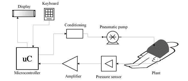
The system is composed by different pneumatic, electromechanical and electronic modules. Figure 2 shows a schematic diagram of the components. The plant that includes the cuirass and the subject, a pneumatic pump (12 V, 15 A, maximum pressure of 150 psi with an airflow of 20 L/m) that is the actuator of the system and control of the entire system that includes, a pressure sensor (MP3V5010DP, 0 to 10 Kpa) that records the pressure in the cuirass, an amplifier of the pressure signal, a FRDM-KL25Z (uC) card, a keyboard for information input and a display screen.
In this system, the variable to be controlled is the pressure inside the cuirass since of its stability depends the compliance computation. The first step was the plant identification, which was performed in open loop, filling the cuirass of air with a step function until reaching a stable operating point and recording the values of the pressure signal with one subject breathing at rest. The signal was filtered low-pass with 0.2 Hz cutoff frequency, in order to eliminate noise produced by the subject's breathing rate. With the system response data, the Matlab® pidTuner tool was used, which allowed to identify the plant and design the PID controller.
After obtaining the values of the constants Kp, Ki and Kd, corresponding to the proportional, integrative and derivative parameters of the PID controller, the control within the electronic system was implemented through by Eqs. (1), (2), (3) and (4).
 (1)
(1)
 (2)
(2)
 (3)
(3)
 (4)
(4)
Eq. (1) describes the output of the controller (u n ), which depends on the previous output (u n-1 ), the current value of the error (e n ) and their previous values (e n-1 , e n-2 ), which were obtained from the difference between the control target value and the sensor measurements. The coefficients (k 0, k 1, k 2) were determined from the proportional, integral and derivative parameters by Eqs (2), (3) and (4). With a sampling frequency of 10Hz, the control output, the error and the recording of the pressure signal are updated. Figure 3 shows a flowchart describing the process implemented in the microcontroller to controller action each time a new patient is instrumented with the cuirass or a different pressure is applied.

2.3 Device performance assessment
Experimental design
Following approval from the Ethics Committee of University Investigation Center (SIU by Spanish acronym) of the University of Antioquia five male subjects were enrolled in this study, age of 23±4.64 years, height of 173.8 ± 5.97 cm and weight 75.84 ± 11.96 Kg. All of them gave written informed consent. The criteria for study subjects selection were, Inclusion: male sex, adults and body mass index less than 30. Exclusion: smokers, people who have ingested alcohol 48 hours before, who use hallucinogens, people under medical treatment, with electric implanted stimulators or with thoracic trauma.
All of participants were connected to mechanical ventilator Hamilton C1 (Hamilton Medical, Bonaduz, Switzerland) with a noninvasive oronasal mask. The ventilator allowed the acquisition of flow, airway pressure and volume signals with a sampling frequency of 1024 Hz. During 3 minutes the subjects were ventilated in spontaneous mode, in which they were not using the device to guarantee the coupling to mechanical ventilator. After that, the cuirass was adjusted to the chest and abdomen of the subjects with a strap system, avoiding leaks as possible. Records were made with pressures of 10 and 20 cmH2O during 3 minutes each.
Compliance of respiratory system
Compliance of respiratory system was calculated in both pressure levels in order to validate that pressure changes in the cuirass imply proportional compliance changes in the respiratory system. To calculate the compliance (C) the Eq. (5) was used, obtaining the variables with an occlusion maneuver at the end of inspiration (see methodology details in [14])
 (5)
(5)
Where VT is tidal volume delivered by the mechanical ventilator. PEEPt is total positive pressure at the end of expiration, which is defined as the summation of the positive end-expiratory pressure applied by the ventilator (PEEP) and the intrinsic end-expiratory pressure (PEEPi) developed in patients due to dynamic hyperinflation [15] and Pplat is the plateau pressure obtained during the occlusion maneuver.
3. Results and discussion
The device for the simulation of restrictive pathologies presented in this article, consists of a control system that allows to modify and maintain a level of pressure on chest and abdomen. This pressure generates a decrease in the total compliance of the respiratory system, due to the parallel summation of the artificial compliance value created by the cuirass and the compliance of the respiratory system of the subject at rest.
The device had mainly two stages of design, the cuirass that with the subject represents the plant and the system of pressure control. Figure 4 shows the cuirass overlapped to a subject on which it had high adjustment, allowing the system to maintain the desired target pressure. However, in some cases, limitations were found in the size of the cuirass and the adjustment of the silicone to different body structures, since there were cases in which leaks due to the width of the thorax were found. These limitations could be diminished using a silicone with a greater surface area in contact with the skin achieving a tightness between the subject and the cuirass.

Figure 4 Photograph of the designed device superimposed over the chest and abdomen of a healthy subject under noninvasive mechanical ventilation
With the volunteer a filling of the cuirass was carried out with the maximum power of the pump, in order to identify the plant. Figure 5 shows the response to the step obtained before and after applying the filter that eliminates the noise produced by the ventilation of the subject.

Figure 5 Step response of the system, in (a) the pressure obtained is presented and in (b) the filtered signal used in the identification process. A typical overshoot in systems of second order or higher can be identified
With the open-loop system response and the use of the Matlab pidTuner tool, the plant was identified and the PID controller was designed with a 65.72% of fit between real response and identified plant’s response. The transfer function of the plant is shown in Eq. (6) and the controller in Eq. (7), with Kp, Ki and Kd, equals to 0.1127, 2.054, 0.064 respectively.
 (6)
(6)
 (7)
(7)
In order to know the behavior and stability of the system found, the step response and the Nyquist diagram were determined to the system, which are presented in Figure 6.

Figure 6 Identification of the plant using the pidTuner tool of Matlab. (a) the system response with the PID controller compared to the real open loop response, (b) the Nyquist diagram of the closed loop system
As part of the evaluation of the performance of the device, two levels of pressure were exerted on the chest and abdomen of five healthy subjects, calculating for each level the total compliance of the respiratory system from Eq. (5) and comparing with the value at rest. Figure 7 presents the result obtained by the system when selecting as objective pressures 10 and 20 cmH2O inside the cuirass for one subject as example of pressure control. The values of compliance for each pressure level are presented in Table 1. Taking into account that the value at rest corresponds to the compliance obtained without wearing the device and the value of 0 cmH2O corresponds to the compliance obtained after adjusting the cuirass with the system of straps on the chest and abdomen of the subjects.

Figure 7 Pressurized system response in one volunteer with 10 and 20 cmH2O target pressure respectively. The effect of the controller on the maintenance of the pressure and on the increase of the speed of response is evidenced
Table 1 Assessment of the variations of the compliance of respiratory system according to changes in the pressure in cuirass

According to the results of Figure 6, it can be observed that the control system identified is a stable system to frequencies minor than 0.71 rad/seg. Concerning the range of unstable frequencies, the pump doesn’t work to those higher frequencies, therefore, the unstable region has not influence. In addition, the controller allowed to reduce the over-impulse of the transient response of the system. The reduction of the over-impulse can also be seen in Figure 7, not exceeding a value of 8% of the desired pressure, whereas in Figure 6 there is an over-impulse slightly greater than 50% of the desired value, which can cause problems in the ventilation of the subject.
Also, it can be observed an oscillation in both curves of the Figure 7, this oscillation is due to the breathing of the subjects, i.e. when the subjects were in an inspiration phase, the diaphragm was contracted, a vacuum in the chamber was generated and therefore a negative pressure during the rest can be observed. On the other hand, when the subjects were in an expiration phase, the diaphragm was relaxed and the pressure in the chamber raised, this is the reason why in some parts of the curves the reference pressure was overcome.
The system used to control the pressure, had a good performance, with a settling time of 6 seconds, the system guarantees a fast control pressure with a steady-state error of 2 cmH2O due to the changes in the breathing of the subjects. On the other hand, the delay time was close to 0 seconds, which confirms the fast response of the system.
As can be seen in Table 1, pressure variations of the order of 10 cmH2O, generate percentage changes comparable between all subjects. In the review presented by M. Eberlein et al. [11], are related different studies where CWS was used, identifying reductions of up to 58% in compliance values, in spite of, the same variation was not achieved for all subjects in the same experimental study. In our case, a change of 34.5 ± 9.4% was achieved at a level of 10 cmH2O and a change of 46.8 ± 5.7% was achieved at the maximum pressure level (20 cmH2O). In none of the cases a 10% deviation was exceeded, which suggests that the system allows to achieve a constant and relatively comparable compliance for all subjects, allowing to evaluate the ventilatory response at various levels of restriction.
4. Conclusions
In this article, we presented the design, manufacture and performance tests of a system for controlled variations of thoracic compliance, in which, unlike the systems reported in the literature, it is possible to know the change applied on the thorax. The second order structure of plant identification allowed to design and implement a controller whose performance is adjusted to the needs.
A weakness of this system is that its use is restricted to a narrow population segment and its use in obese, very thin or female people will require changes in dimensions or even different shapes.
The results show that this device will allow to generate artificial variations of respiratory compliance useful in the development of processing techniques that in the future will be able to estimate the pulmonary compliance of patients with restrictive and obstructive diseases.

