Services on Demand
Journal
Article
Indicators
Related links
Share
CT&F - Ciencia, Tecnología y Futuro
Print version ISSN 0122-5383On-line version ISSN 2382-4581
C.T.F Cienc. Tecnol. Futuro vol.1 no.5 Bucaramanga Jan./Dec. 1999
DYNAMIC SIMULATION OF A FURNACE OF STEAM REFORMING OF NATURAL GAS
Abstract
Steam reforming of natural gas is a very important industrial process in refineries and ammonia and methanol plants. Hydrogen is produced by reforming methane with steam. This hydrogen is essential in the hydrotreating process in the refineries thus, it is important to supervise and control the performance of the hydrogen plant. Mathematical models of refineries and chemical plants are used to simulate the behavior of the process units. However, the models especially of reactors like reformers, are not very reliable. This paper presents a dynamic model of a furnace reactor. The simulation results are validated with industrial data.
Keywords: steam reforming, natural gas.
Resumen
El reformado de gas natural con vapor de agua es un proceso muy importante a nivel industrial en refinerías y plantas de amoníaco y metanol. El hidrógeno es producido principalmente por reformado de metano y es esencial en refinerías, en los procesos de hidrotratamiento, por esta razón es importante supervisar y controlar el desempeño de las unidades de hidrógeno. Actualmente en las refinerías y plantas químicas se utilizan modelos para simular el comportamiento de las unidades de proceso. Sin embargo, los modelos especialmente de reactores como reformadores, no son muy confiables. Este artículo presenta un modelo dinámico de un horno reactor de reformado, que considera las reacciones y los procesos de transferencia de masa y energía, que se llevan a cabo en este reactor. Los resultados obtenidos en la simulación son validados con datos a nivel industrial.
Palabras clave: reformado con vapor, gas natural.
INTRODUCTION
The changes in the legislation for fossil fuels have affected the hydrogen balance in the refinement industry. The hydrogen demand has increased significantly due to the high hydrotreating degree demanded to fulfill the environmental regulations.
The plants that produce hydrogen by steam reforming process diverse feeds ranging from natural gas to mild distillates (gasoils) and residuals (Chauvel and Lefebvre1989).
The steam reforming of methane is the most economic and more broadly used process. The process gas contains hydrocarbons with traces of sulfur that are eliminated in the desulfurizer of zinc oxide (John Mc Ketta, 1984). The gas outgoing from the desulfurizer is mixed with steam and is fed to the furnace (reformer) where it is converted into hydrogen, and carbon monoxide and dioxide, in presence of Niquel catalyst, to temperatures between 978 K and 1143 K (705 and 870°C), pressures between 2070 kPa and 4120 kPa (300 and 600 psi) and molar ratios (steam/carbon) between 2 and 9. The reaction gas outgoing from the reformer is passed through two converters of high and low temperature where the carbon monoxide, by means of chromium and copper produces more hydrogen and carbon dioxide. Later on, the carbon dioxide is absorbed by a solution of MEA (mono ethanolamine).
Finally, the treated gas (that contains small quantities of carbon oxides) is passed through the methanizer where the carbon oxides are hydrogenated to methane in presence of a catalyst.
Many authors have developed dynamic models for fixed bed chemical reactors. Oblad and then Grover (Murray and Snyder, 1985), presented a model of a steam reformer of methane, which considered the transfer of heat and the analysis of the kinetics of the reactions. The formation of coke is generally very small and can be considered negligible under the industrial operation conditions. This model assumes one-dimensional flow (piston) for gases in the reformer's tubes and considers a first order kinetic equation of the rate of reaction for the partial pressure of the methane. The equation of the inverse reaction rate is also considered in the balance of reactions. The results are well adjusted to the data obtained in a pilot plant.
In 1968, Hyman developed a similar model. However, it differs in several aspects. To evaluate the inverse reaction rate to produce methane it uses a derived expression from the law of action of moles, instead of a first order equation. It also considers flow piston for the gases, and a profile of the external temperature of the wall of the tube, instead of the flow rate of the gases. The model can be used to analyze the reforming of heavy hydrocarbons. Again the results of the model adjusted well to the plant data.
In 1979, Olesen and Sederquist considered a double tubular flow in crosscurrent (DCCF) (Murray and Snyder, 1985). This design is also described by Smith and Santangelo in 1980. In this design the quantity of required heat decreases. It is considered the formation of coke. This model keeps in mind the effects of axial and radial mixing. The results are well adjusted to the plant data. However, given the complexity of the model, the precision of its results is not comparable to those obtained with models of flow piston.
In 1979, Chandra and Deoki developed a method to calculate the heat transfer of the oven of the reformer.
They considered the transfer of total heat of the flames and the flue gases at the same time with the heat transfer of the reaction gases, inside the differential section of the tube reactor. The results obtained when simulating the reformer reactor using this method are adjusted very well to the plant data.
In 1978, Harth et al. introduced to the reformed technology a novel application. This is the combination of the methane reformer with a nuclear reactor to high temperature, cooled with steam (HTGR) (Murray and Snyder, 1985). It offers an excellent means for transporting thermal energy on big distances. In the catalyst, the reforming reactions can be reverted liberating energy. An interesting point of this study is the use of the design DCCF. The calculations are based on global balances and data of the catalyst.
In 1982, Murray and Snyder developed a kinetic model of a methane reformer with steam as a design tool and analysis to condition systems of combustible cells. This model includes options to consider effects such as: reaction type, geometry, arrangement of flow, and transfer of heat. The results of the model are adjusted well to the experimental data.
In 1989, Plehiers and Froment published the development of a heterogeneous unidimensional model for a steam reforming reactor. The model considers the presence of partial intraparticle pressure gradients and the distribution of temperature in the furnace and in the reactor simultaneously. For heat transfer in the furnace, it uses a simulation program of a standard furnace, based on the area method. To determine the view factors it applies Monte Carlo simulation techniques. It considers the location of burners, the absorption and the radiation emission. The distributions of temperature in the furnace and the composition simulated are excellently adjusted to the industrial data.
To analyze the dynamic behavior of the reforming Such model represents the physical and chemical phenomena that take place in the process. The dynamic simulation of the tubes and the furnace of natural gas reformer is carried out, using a heterogeneous one-dimensional model. To evaluate the reaction rates, the kinetic expression proposed by Haldor Topsoe (Chandra et al., 1979) is used. To determine the temperature of the process gas, three energy balances are applied: inside the control volume, in the wall of the tube, and in the furnace. For the energy balance in the metallic wall, it is assumed that the furnace area is much bigger than the tubes area and that these are completely inside the furnace (Smith, 1985).
These models are essential in the study of industrial units where the experimental tests to analyze the effect of disturbances or changes in the manipulated variables or controlled are very limited, undesirable and they can drive to severe alterations of the performance of the unit. The results of the model were validated with industrial information.
DEVELOPMENT OF THE DYNAMIC MODEL
In the development of the model, the following considerations are taken into account (Elnashaie et al., 1988):
- The multitubular furnace-reactor is vertical and the heat is transferred by radiation and convection of the combustion gases.
- The operation conditions in all the tubes are similar
- Flow piston of the process gas in the tubes (length to diameter, L/di >100).
- The heavy hydrocarbons are transformed into methane at the entrance of the tubes.
- The gradient of the profile of radial temperature is insignificant.
- The temperature of the catalyst particles is uniform and similar to that of the process gas (relationship diameter of the tube to diameter of the catalyst particle, di /dp = 10).
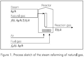
- There is no coke deposition in the catalyst. The simplified process sketch is presented in the Figure 1.
Reactions
Under the operating conditions of the commercial units, the following reactions are usually considered:
- Production of monoxide of carbon from methane

- Production of dioxide of carbon, water gas shift Reaction:

- Conversion of paraffin's to methane:

- Equivalent methane. If the feed is composed of nk moles of Ck H2k+2 per hour, then:

- Equivalent hydrogen. The moles of hydrogen, after hydrotreating, are obtained by:

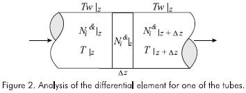
Because the temperature and the concentration of the gas vary continually with the distance from the entrance of the reactor, a section of the tube of a length Δz is considered as control volume. In it the properties are assumed constant, see Figure 2.
Molar balance of components
The molar balance of the components can be established since the flow and the composition of the process gas (natural gas and steam) are known.
For methane, CH4
The partial differential equation for the molar balance of methane at any point of the tube in any instant of time, is:


the equation that describes the molar balance of methane around the control volume of length Δz, at any distance of the entrance of the tube, is:

For dioxide of carbon, CO2
The molar balance of carbon dioxide, around the control volume of length *z, at any distance of the entrance of the tube, is:

The reactions for carbon monoxide and dioxide production, are used to evaluate the reaction rates according to the kinetic expressions proposed by Haldor Topsoe (Chandra, 1979):


The constant of specific rate for RCH4 and RCO2,are obtained from the following expressions:


The equilibrium constants for the production of carbon monoxide and dioxide are calculated by:


For the stoichiometry, it is assumed that the moles of each component accumulated in the control volume are insignificant. The moles of steam at the exit of the control volume of length Δz can be calculated by:

X(t) is defined as the converted moles of equivalent methane:

The moles of hydrogen to the exit of the control volume can be calculated by:

The moles of monoxide of carbon to the exit of the control volume are determined by:

The total moles leaving the control volume are obtained by:

Nilz is the molar flow of component i at the entrance of the differential element and is given by the previous element. Nilz±Δz is the flow molar of component i leaving the differential element and is obtained by:

It is assumed that the gas product is an ideal gas for the industrial conditions of temperature and pressure of these processes. The fraction molar of component i can be calculated by:

For the equation of ideal gases:

Unsteady state energy balance
To evaluate the temperature of the process gas, it is necessary to develop three energy balances: inside the control volume, in the wall of the tube, and in the furnace.
Energy balance in the control volume
Taking as reference state, for the enthalpy and internal energy, the elements that constitute the reactants and the products to 298 K (25°C) and the elements that do not react to a convenient temperature, and the pressure of the system, the energy balance in the differential element Δz, can be written by:

Calculation of the heat transfer coefficient
The model uses a heat transfer coefficient hi(t), calculated from the correlation of Beek (Hyman, 1986):

Balance of energy in the wall of the volume of control (Smith, 1985)
If it is assumed that the area of the furnace is much bigger than the tubes area, and that these are completely inside the furnace, the energy balance can be expressed by:

Balance of energy in the furnace

Drop pressure through the bed of catalyst
Using the equation of Ergun (Hyman, 1986):

Results of the model
The dynamic simulation of the furnace - reactor of steam reformer of natural gas, is carried out using the software MATLAB (version 5.2) and the toolbox SIMULINK (version 2.0). The tube reactor was divided into 8 sections of the same length. To solve the differential equations, variable step method ODE23S (Stiff/Mod Rosenbrock) was used.
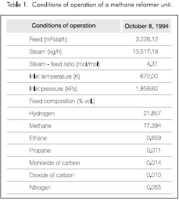
To verify the results of the model, the conditions of an industrial plant were used. There are presented in Table 1. The composition of the gas fuel and feed is the same.
Figures 3 and 4 present the results obtained by the simulation. Figure 3 shows the distribution of the molar composition along the tube. The molar fraction of the methane and steam decrease continually through the reactor. The amount of hydrogen, monoxide and dioxide of carbon increases with the length of the tube reactor.
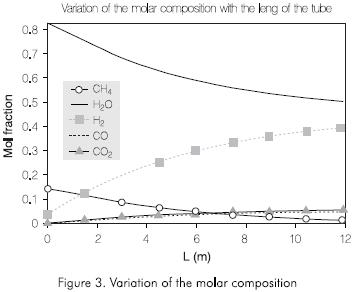
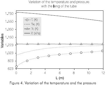
Figure 4 shows the variation of the temperatures of the wall of the tube, of reaction, and the pressure along the tube. The external temperature of the tubes increases continually with the length of the reactor. the Same behavior is observed in the reaction temperature. The pressure decreases along the reactor. The profile of these variables obtained by simulation is adjusted to the operation conditions observed in this process.
Table 2 shows the comparison between the plant data and the results of the model.
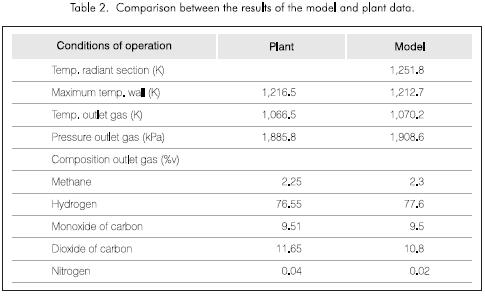
The temperatures and the composition of the dry gas product obtained by the model are adjusted excellently to the conditions of the industrial plant. The pressure drop through the catalyst bed can be used to test the activity of the catalyst.
The verification of the dynamic part of the model will be presented in a next paper in which different control strategies will be analyzed like cascade, feed- forward and multivariable control to optimize the process of industrial reformers.
CONCLUSIONS
In this article, a review of the state of the art for the process of steam reforming of methane was made. A kinetic model was used to evaluate the reaction rates proposed by Haldor Topsoe (Chandra, 1979). A heterogeneous model of the reactor based on the variation equations representing the transport phenomenons is carried out in this process. To evaluate the temperature of the process gas three energy balances were developed: inside the control volume, in the metallic wall of the tube, and in the furnace. In the energy balance in the wall of the tube it is assumed that the furnace area is much bigger than the area of tubes and that tubes are completely inside the furnace (Smith, 1985). In the solution of the model, the technique of differential balances of mass and energy was used.
A model based on fundamental principles can be used to evaluate the distribution of compound and temperature throughout a reactor, with great precision.
This makes the model a powerful tool in the design or optimization of reaction furnaces. The valuable information generated by the model contributes to better knowledge of the process.
REFERENCES
Alatiqui, I. M., Meziou, A. M. and Gasmelseed, G. A., 1989. "Modelling, Simulation and Sensitivity Analysis of Steam Methane Reformers", Int. J. Hydrogen Energy, 14: 241 - 256. [ Links ]
Chandra, S. and Deoki, S. 1979. "Simulation of Side Fired Steam-hydrocarbon Reformers", Ind. Eng. Chem. Process Des. Dev., 18 (1). [ Links ]
Chauvel, A. and Lefebvre, G., 1989. Petrochemical Processes 1 Synthesis - Gas Derivates and Major Hydrocarbons, Editions Technip, Second Ed, Paris. [ Links ]
Elnashaie S. S. E. H., Al-Ubaid, A. S., Soliman, M. A. and Adris, A. M., 1988. "On the Kinetics and Reactor Modelling of the Steam Reforming of Methane - A Review", Journal of Eng. Sci., 14 (2): 247 - 273. [ Links ]
Grover, S. S., 1970. Hydrocarbon Processing, 49 (4): 109. [ Links ]
Harth, R., Kugeler, K. et. al., 1978. Nucl. Technol., 38: 252. [ Links ]
Hyman, M. H., 1968. "Simulate Methane Reformer Reactions", Hyd. Procs., 47 (7): 131 - 137. [ Links ]
John Mc Ketta (ed.), 1984. Encyclopedia of Chemical Processing and Design, Marcel Dekker Inc., vol. 20, New York. [ Links ]
Murray, A. P. and Snyder, T. S., 1985. "Steam Methane Reformer Kinetic Computer Model with Heat Transfer and Geometry Options", Ind. Eng. Chem. Proc. Des. Dev., 24 (2): 286 - 294. [ Links ]
Oblad A. G., 1967. Oil and Gas Journal, 54 (16): 164. [ Links ]
Olesen, O. L. and Sederquist, R. A., 1979. The UTC Stream Reformer, United Techologies Corporation, Windsor, Ct. [ Links ]
Plehiers, P. M. and Froment, G., 1989. "Coupled Simulation of Heat Transfer and Reaction in a Steam Reformer Furnace", Chem. Eng. Technol., 12: 20 - 26. [ Links ]
Reid, C. R., Prausnitz, J. and Poling, B. E., 1987. The Properties of Gases & Liquids, 4th De. Mc Graw Hill. [ Links ]
Smith, C. A. and Corripio, A. B., 1985. Principles and Practice of Automatic Process Control, 1st Ed. John Wiley & Sons. [ Links ]
Smith, W. N. and Santangelo, J. G., 1980. ACS Symp. Ser., 116: 147 - 176. [ Links ]
APPENDIX
Chemical and physical properties
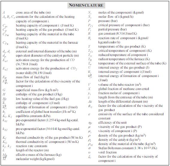
For the calculation of chemical and physical properties the expressions proposed by Reid, 1985 were used.
Molecular weight
The molecular weight of the process gas is obtained by:

Partial pressure
The partial pressure of each component can be obtained by:

Internal energy
The internal energy of the process gas accumulated in the differential volume is calculated by:

The internal energy for the methane, assuming an ideal gas, is obtained by the following expression:

Heat capacity
The gas mixture is evaluated by:

The heating capacity of for the component i is given by:

Enthalpy
The enthalpy of the process gas to the entrance of the differential element, is obtained by:

The enthalpy of each component can be determined by:

Mass rate
The superficial mass rate, is defined as:

Viscosity
The method of Wilkes is used to evaluate the viscosity of the gas product:


The viscosity of each one of the components of the gas product, is determined by the method proposed by Lucas:


For the hydrogen:

For the other components 
Thermal conductivity
To evaluate the thermal conductivity of the gas product used the expression proposed by Mason and Saxena:

The thermal conductivity of each one of the components of the gas product, is evaluated by the method proposed by Stiel and Thodos:

The density of the gas product, is calculated for:


