


 English (pdf)
 Article in xml format
 Article references
 Send this article by e-mail
 Cited by SciELO
  Cited by Google
  Similars in
SciELO
Similars in
SciELO  Similars in Google
 Permalink
Introduction
Road infrastructure is the main card towards development for a country 1 and must be a priority regarding resource investment 2. In 3 is mentioned that roads fill a social, economical and geoestrategic role. Construction methods have been changing with the years as well as economic dimentions and challenges in engeneering. Added to it, the consequences of climate change, lack of planning and incorrect use of the territory, causes that infrastructures are vulnerable to mass movements, erosion or floods, causing social, economic and mobility problems due to destruction or partial blockages of roads. Traditional solutions are not enough and can´t mitigate the emergencies in short time.
Giant Geotextile Bags (GGB) are defined, according to specifications 4, as: ¨Big format polyhedrons to be filled with dirt made out of high module geosynthetics; manufactured with polyproline, polyester or at least two high resistance and tenacity synthetic polymer mixture with high resistance, UV treatment to chemical substances and biological inert¨.
It is possible to find them under the names of Megabags, Soilbags or Jumbobags. According to providers they can vary according to geometric specifications, usage or application. During the 70´s the concept of sand geo-containers began (Geotextile Sand Containers) as an alternative for costal defense structures, staring in the Netherlands when using sand bags for the construction of Pluimpot Dam 5.
In 5,6, geotextile is defined as a type of geosynthetics, that is fully elaborated with polymers with threat or fiber appearance used as contact with the ground or rock. Some properties are described in 5.
Physical and Mechanical characteristics Study.
It´s been shown that the friction angle is directly related to the bag resistance against extreme load 7. Same way, 8 study and that from Xu et al. 9) show that soil bag has a high resistance (increments its load capacity) under external loads, and it might contribute to the traction strength of the bag. That type of structures has a ¨high tension confinement that limits the lateral displacement and reduces the foundation settlement” 9.
On the other hand, Ansari et al. 10, present finite elements to analyze its behavior under vertical compression and shearing. Same as Cheng et al. 11, they present that the load capacity increases when wrapping granular soil in geotextile bags due to the effective restriction of ground’s dilatation. The load capacity is boost when wrapping granular soil in geo-textile.
The shape of the sliding surface has influence over friction resistance between the soil bag layers Fan et al. 12. Fan et al. 13 study showed a containment constructed wall to analyze the slippage stability, and concluding that “the active soil pressure acts upon the wall built with sand bags on their final stage is not linear, but can be calculated from the strength balancing forces of a differential element”. In a geotextile bag system, the units disposition in its intermediate layers, and the filling material properties is related to the bags’ cutting characteristics 12.
Research regarding applicability.
There are studies around the use of soil bags to reduce vibrations and energy spreading. Wang 14 shows that “total soil bag percentage, and the energy use of its internal particles, exhibit an obviously wavy shape, that varies along loading and unloading. Its percentage overpass a 75% of the total energy meaning that the soil bag could have a better energy deplete effect” 14.
Wang 15 research found that the side expansion of containment wall on expansive ground could be positively through the use of soil bags. Another study by Li et al. 16, highlights the frosting prevention on channels treated with soil bags: it happens due to the preventive effect of soil bags “as it inhibited the raising of capillary water and water layer while having a reinforcement effect”
Antón 5 mentions diverse applicability’s of geotextile structures, among them: coatings, walls, hill slide protection, undermining guard; external dune ground, dames, breakwaters, external levee or reef.
There is also evidence of geotextile bags usage for ashes dams to store flying ashes -charcoal subproduct after burning-. Li et al. 17 studied that bags filled with ashes or sand have a compression resistance: “the main dam built with soil bags can effectively hold filling ashes, and the pile dam reinforced with soil would remain stable even on a 1:1.5” slope 17.
Geo-bags system “has the capacity to simulate rocks, masonry elements or containment walls cement. Therefore, in its capacity to contain particles and ease water draining, geo-bags have the possibility to hold subventions, settlings and push-up strengths or hydraulic cut efforts” 6.
Soil Bag technology has been used in the construction or levees in China, where it has a global stable effect when combining ground settlement effort, and the sub-dam stabilization and collaborative draining. 18.
Tang et al. 19 highlights its utility when reinforcing slopes and buildings construction foundation due to its high compression capacity, to which is added the results of the study where is possible to see the system’s great results against liquefaction. Adding to it, Liu et al. 20, show that soil bags have high load capacity and a significantly stable deformation behavior capacity under cyclical load.
Geotextile Bag usage experiences
Table 1 represent some succeful experiences using geotextile bags.
Table 1 Geotextile Bags usage experiences
| Country | Case | Reference |
|---|---|---|
| Perú - Piura | 3.2 Km recovery of fully submerged road due to its proximity to a natural lake. | Ibañez 6 |
| China - South/North SNWTP project | Real field test of a 60 m long slope of a ground canal with expansive/rock reinforced with soil bags. Test included raising and low levels of water as well as natural and artificial precipitation. | Liu et al. 21 |
| Bangladesh | Use of geotextile bag to stop erosion caused by Dharla river. 250Kg bags were placed over the meander section when water began to reach flooding levels. | Dip et al. 22 |
| Colombia | Bengala (Garzon-Neiva road at Km 21). Crespo Tunnel (Cartagena). | Information about installation and functioning given in present study results chapter. |
Giant geotextile bags are a: “confinement system for ground to be used as a hydraulic structure on contention and protection constructions for roads, coast, river bank or harbor areas” 4.
Giant geotextile bags are under the technical regulations of new technologies developed by the National Road Institute (INVIAS as in Spanish) in partnership with Cauca University linked to the inter-administrative agreement No. 1633 from December 26, Giant Geotextile Bags (GGB), Article No 685 Chapter 6 - Structures and drains 2020.
Methods and materials - study cases
Study case: Bengala
First study case is related to the terracing and slope stabilization in Bengala (Huila, Colombia), were in June 29, 2019, a 21 Km long bank road was lost (National Road No. 45)
Initial Situation
Slope happened on the right side of the Barrialosa stream, starting on the right side of Barrialosa bridge. Geological formation around the slope is Giant formation (TGI) which is formed by intersperse of sand rock, tuff, claystone, and high levels of pyroclastic ashes and lapilli. Slope layers are mainly of volcanic origin and of the material used for contention structure. An intervention of the structure is made to allow transit in two stages. First one to allow movement on one side of the road; and a second in 15 days time to allow vehicle flow on one side 23. Later it is determined the time of total development and opening in both ways by a length of 4 months. Figure 1.

During this time both sides of road were worked on as well as the full slop stabilization over the Barrialosa Stream. Implemented technology was key to work over the project in the least possible amount of time. Geotextile bags used were from the Megabags brand, with a friction angle higher than 45 degrees, and its apparent size reduced pore is what allows that the material with contained ashes won’t wear out.
Design
Design is made using local materials and Megabags. Set parameters are presented on table 2.
Table 2 Used material characteristics for GGB modeling.
| Material | 𝛾(𝑘𝑁/𝑚3) | c’(kPa) | 𝜙(°) |
|---|---|---|---|
| GGB (Megabags) | 20 | 20 | 24 |
INGETEC 25
It is highlighted that the friction angle for Megabags units is 24 degrees, although, the value is actually 45 guaranteeing an additional safety factor during installation process. Figure 2.

Figure 2, shows the model through SLIDE software, which allows to evaluate on various methods the overall structure stability by limiting balance. Then, using the Fallenius method is possible to determine a safety factor of 1,73. In this case, units a modeled as if the ground has a homogenous behavior using previously described characteristics. It is important to highlight that a closer model to such elements would be by adding the geotextile layers and generating new correspondent friction angles. The ground, in its interior part of the unit is in rest and confined as its behavior is passive, not active for the different models to be made with this software.
Construction Process
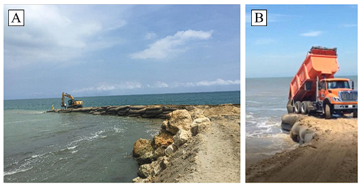
During first stage of construction, bags were thrown-installed to guarantee an operational area allowing appropriate work to operate with the units. When the lower platform was finished, bulldozers were moved to the platform to begin with the filling of units using formwork instead of dump trucks as initially done. Like that it was possible to complete installation successfully. First stage to allow one side vehicle transit last for 14 days 25. Figure 3.

Figure 3 Bengala road recovery first stage 26Dump installation (Figure A and B). Formwork installation (Figure C)
Second stage (Figure 4) started when the dam lowered its levels. The full setting of the hydraulic structure was made after drained granting the re-shaping of the whole construction. The total time of construction happened in 6 months due to pandemic. It was one of the fewest construction sites still active during lockdown.

Initial situation
Submerged wall between seawalls of the Crespo Ring Road project was an integral segment on the freeway construction project towards the sea. One of the key points was to set a dry-wet beach across Crespo tunnel. With 140 meters width, a protection side slum wall of 1670 m long connecting all 7 seawalls.
There is a strong sea current that disallow sand holding rapidly weathered by the sea. To achieve that, the beach gets settle through time Megabags technology was used. Then, adopting an offshore structure to support the wave energy breaking it from the outside. Same way, it is worked the rock seawall seal that is considered for its high porosity generating suction currents that might be unsafe for swimmers.
Design
The greatest return-current and maximum surge reported were considered for the submerged structure design. Same way, it was also included the historical last 50 years variation of tides reported by DIMAR-Colombia. It is considered a useful life spam of 25 years for the structure.
It is important to highlight that the minimum crest elevation allowed for the structure to be functional should be 1.44 m below sea level (BSL), opening a 1.5 m BSL tolerance. On the closed seawalls, it was decided to increase the barrier to stop suction current formation and to reduce height from 1.25 m and 0.75 m, see Figure 5.
Sea tide delta is 0.5m, which implies a significant variation between low and high tide. Given that the damaging tide is that from the lower level, it was set to use a of 0.35 over the typical media tide level (mtl). Like that, and with the modeling done of used sand can be determined the followed beach profile. It is important to mention that, within the design and modeling calculations, is possible to notice that it will always generate a hydraulic jump that, besides holding the structure, has a depth big delta. Figure 6.


Figure 7 to determine the structure stability, the un-stabilizing forces are determined over the stabilizing ones giving a safety factor. For it, each of the different thrust are considered: Sand thrust, hydrostatic forces by the sea level, and thrust by the dynamic pressure delta happening on both sides of the barrier. The shift of the momentum produced by wave impact and its speed must be included at this point and will determine the total thrust that the structure must hold on.

Following parameters were considered (Table 3) to stablish the minimum width required: Density of GGB of 1.6 T/m3, operational depth of 3, 3.5 and 4 m; previously set isobath, and a slope safety factor no less than 1.2.
Construction Process
The submerged wall construction in Crespo, was all done by dumping (Figure 8), with specialized trained technicians that instruct the dump truck on it. Next, diggers will place units if needed on the exact working spot. Units were filled with sand and then twice sealed with double needle sewing machine making sure of an appropriated close, due to their exposure to elements on the project lifespan.
As seen on Figure 8, we can observe that in order to build the structure, is important to move over it, and because of that is that the top units must be cut once the totality of the barrier is set to guarantee the design’ stablished isobath.
Results and discussion
In the Bengala case, the Megabags structure had reported a settling of 8 cm measure with a probe until the 20th of October, 2021 showing an acceptable rate and the road functionality is in good shape. The terracing built with 50/50 material has a total settling of 15 cm, also under acceptable ranges. The structure has supported rising and lowering of levels 4 times after construction and up to present the structure is stable. The slope is fully cover with vegetation and the only exposed units are those near the stream bridge.
For the Crespo submerged wall case, the performance may be observed from the following series of pictures with details of the construction process and the result of the dry and wet beach allowing the road protection against marine wear out. Figures 9, 10, 11, 12, 13.


Figure 11 Satellite Images of construction site. December 2013. Final stage of seawalls construction 32


By using only seawalls, the beach is tried to be stabilized, but a considerable erosion begins to show specially between the first two seawalls compromising the tunnel, then it was decided to protect the structure with a GGB (Megabag) marginal barrier. Figure 14, 15, 16, 17


Images show how coastal dynamic changed and produced the weave breaking over installed wall site favoring the beach formation. After initial construction a relevant contribution with sand to help a greater sedimentation of the first stage of process. Figure 18 and Figure 19.


It is possible to notice the wet-dry beach is still stable through time without showing major changes and allowing the road be protected. Figures 20, 21, 22, 23.


It is clearly visible how the immerse wall produced sedimentation and keeps the beach steady through time.
Submerge wall of Crespo in its final stage, exhibit a steady structure over time granting a structure with a considerable durability for a 25 years design of useful lifespan. It is important to mention that, given that the structure provides an adequate and final protection on Crespo tunnel, providing a dry/wet beach, the structure, as though in design, has a hydraulic jump over the weave inducing the release of energy offshore, therefore reducing the energy that reaches the beach. Such, produce an important tide inducing significant currents, added to having an important delta of highs for when it overpasses the protection zone of the submerged wall.
It is relevant to mention that a favorable practice would be to push further the submerged wall structure from the shore and deepen it more, guaranteeing it won’t create a safety feeling due to its short depth and suddenly goes dramatically deeper causing great risk areas for swimmers.
From all results of research, is possible to notice that on coastal infrastructures (Crespo Tunnel), the use of giant geotextile bags works in a satisfactory manner controlling erosion as also shown by Antón 5 research. Moreover, required the execution time is lower over conventional structures with also the possibility to use local materials and feasible applicability under water present situations according to Antón 5 and Ibañez 6 studies.
Research also found, that for Bengala study case, the structure during operational stage, had hold rising and low water levels a few times (4 times), and up to the present it still remains stable, to which is demonstrated it efficiency stabilizing slopes as also demonstrated by Dip et al. 22. Also, in same site, an 8cm settle happened, to which is considered as an acceptable value. However, according to Ibañez 6, deformations have been even less than.
Conclusions
Present study and follow-up showed the versatile properties of giant geotextile bags applied to engineering constructions. At qualitative levels, it was possible to demonstrate the restauration process, coastal or slope stabilization, as well as to exhibit the possibilities of using local materials and its practical utilization with the presence of water.
On a quantitative level, it is noted its long-term stability, its geometrical recovery of needed areas, the shorter execution time than in conventional structures. Due to it, Giant Geotextiles bags, having a geotechnical and hydraulic design according to the project, is considered as a reliable alternative.

